Power control of a power amplifier

a power amplifier and power control technology, applied in the direction of rf amplifiers, automatic tone/bandwidth control, gain control, etc., can solve the problems of reducing the efficiency of the power amplifier, so as to prevent the saturation of each amplifier stage, improve efficiency, and limit distortion

Active Publication Date: 2007-03-27
SONY EUROPE BV
View PDF10 Cites 14 Cited by
  • Summary
  • Abstract
  • Description
  • Claims
  • Application Information

AI Technical Summary

Benefits of technology

[0016]The present invention performs power control by regulation of the supply voltage, but in a different manner the conventional supply regulation technique for a constant envelope modulation scheme, as described above. In particular, instead of operating the power amplifier in saturation, the present invention takes advantage of property of some power amplifiers that the gain reduces with the supply voltage. Thus, the present invention uses a power amplifier having a change of gain over the voltage supply range which is at least the required change in output power over the predetermined power control range. As a result, the power control over this predetermined power control range can be achieved entirely by the supply regulation. Therefore the present invention therefore limits or avoids altogether the need to include a variable gain amplifier to change the input power. This in turn reduces or avoids the various disadvantages of a variable gain amplifier as set out above.
[0029]This provides the advantage of improving the efficiency. This may be understood by considering the fact that the actual output power is maintained below the saturation output power across the entire control range of the supply voltage. In general, such back-off of the power amplifier reduces efficiency. However, with this preferred feature, it is possible to minimise the back-off of the output power at the maximum supply voltage in the control range. Consequently, at lower supply voltages in the control range, the rate of reduction of the gain of the power amplifier ensures that the actual output power remains below the saturation output power across the entire control range. At the maximum supply voltage in the control range, by minimising the back-off of the output power, the efficiency is maximised. The maximum supply voltage is the most important part of the control range in which to maximise efficiency, because this is the part of the control range which experiences the highest absolute power loss (for a given efficiency) because the output power is at its highest level. Preferably, from the point of view of maximising efficiency, the gain of the power amplifier and decibels reduces at a rate equal to the rate at which the saturation output power of the power amplifier in decibels reduces.

Problems solved by technology

As a result, it is normally only considered valid for constant envelope modulation schemes because they are insensitive to the gross AM non-linearities associated with the power control technique.
This is because the clipping of the radio frequency output voltage caused by operation of the power amplifier in the saturated region results in AM-AM and AM-PM distortion which is unacceptable in the context of variable envelope modulation (AM: amplitude modulation; PM: phase modulation).
Unfortunately, such backing-off of the input power into the linear region comes at the price of lower efficiency.
In addition, the variable gain amplifier consumes a significant current, typically 20 to 50 mA which further degrades the efficiency of the power amplifier.
The use of a variable gain amplifier has further disadvantages of increasing the die size and limiting the ability to meet the stringent wideband noise requirements for typical wireless communication network specifications such as GSM and EDGE.
However, these implementations are typically associated with a high degree of complexity and do not allow an elegant migration part to the WDCMA specification or other 3G specifications.
Furthermore, the efficiency potential of polar loop techniques for the EDGE specification are often not fully realised due to the current consumption requirements within the inherent correction loops.

Method used


Image

  • Power control of a power amplifier
  • Power control of a power amplifier
  • Power control of a power amplifier

Examples


Embodiment Construction

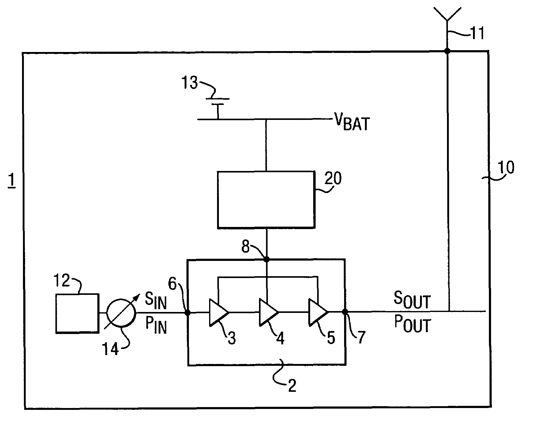
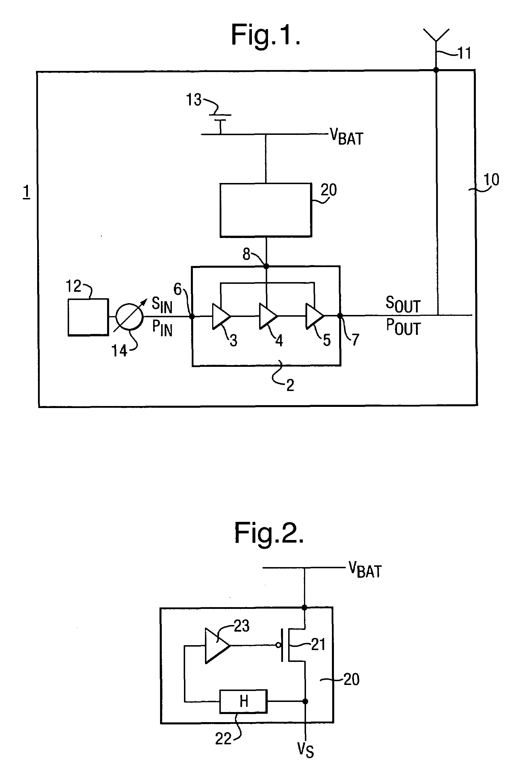
[0043]A power amplifier power control circuit 1 which embodies the present invention is shown in FIG. 1. The power amplifier power control circuit 1 has a power amplifier 2 which comprises three amplifier stages 3, 4 and 5 connected in series. An input signal SIN having an input power PIN is supplied to the input 6 of the power amplifier 2. The input signal SIN is amplified successively by the amplifier stages 3, 4 and 5 to produce an output signal SOUT at the output 7 of the power amplifier 2 having an output power POUT.

[0044]The power amplifier power control circuit 1 is provided inside a mobile terminal 10 for use with a wireless communication network. The output signal SOUT is supplied to an antenna 11 of the mobile terminal 10 for transmission. The input signal SIN is generated by the signal processing circuit 12 of the mobile terminal 10 and is modulated in accordance with the variable envelope modulation scheme of the specification of the wireless communication network in whi...


PUM


Abstract

To effect power control of a power amplifier 2 having three amplifier stages 3, 4 and 5 used to amplify input signals modulated in accordance with a variable envelope modulation scheme, there is used a power amplifier 2 having a gain which reduces as the supply voltage to the power amplifier 2 reduces, and the output power POUT of the power amplifier 2 is controlled by regulation of the supply voltage VS. Taking advantage of the reduction in gain of the power amplifier 2, it is ensured that, in respect of each respective amplifier stage 3, 4 and 5 and at each respective value of the supply voltage in the voltage control range, the output power POUT of the respective amplifier stage 3, 4 and 5 is less than the saturation output power PSAT of the respective amplifier stage 3, 4 and 5. As a result, distortion of the signal is reduced. The power control technique improves efficiency over known techniques of backing off the output power and using a variable gain amplifier stage to control the output power.

Description

FIELD OF THE INVENTION[0001]The present invention relates to power control of a power amplifier used to amplify a signal modulated in accordance with a variable envelope modulation scheme. The present invention has particular application to power amplifiers used in wireless communication networks, for example in accordance with the EDGE specification or the WCDMA specification.DESCRIPTION OF RELATED ART[0002]In wireless communication networks it is necessary to control the power of signals output by the mobile terminals, in particular to minimise inter-channel interference and to conserve power. Such power control may be done by control of the power amplifier used to amplify the modulated signals.[0003]Many early wireless communication networks and in particular the first European digital cellular wireless networks used constant envelope modulation schemes, for example GMSK modulation as used in the GSM specification. The power control techniques used with such constant envelope mod...

Claims


Application Information

Patent Timeline
Patent Type & Authority Patents(United States)
IPC IPC(8): H03G3/10
CPCH03F1/0211H03F3/24H03F2200/504H03F2200/451H03F2200/408
Inventor CLIFTON, JOHN CHRISTOPHERDENNY, SIMONEATON, ANTHONY
Owner SONY EUROPE BV
Why Eureka
Try Eureka