Powered watercraft

a watercraft and power technology, applied in special-purpose vessels, vessel construction, transportation and packaging, etc., can solve the problems achieve the effect of reducing back pressure and adverse effect on engine efficiency, reducing friction drag, and improving performance and efficiency of the m-shaped boat hull

Inactive Publication Date: 2005-01-27
M SHIP
View PDF12 Cites 17 Cited by
  • Summary
  • Abstract
  • Description
  • Claims
  • Application Information

AI Technical Summary

Benefits of technology

[0008] Preferably, the exhaust-venting opening at the vertical step is located intermediate the upper and lower portions of the vertical step where it faces rearwardly from the vertical step. That arrangement results in pressurized exhaust gases being directed parallel to and adjacent to the planing surface in order to create a film of high pressure gas that provides lift and further reduces friction drag. In addition, the entering gas creates a venturi effect that reduces the back pressure and its adverse effect on engine efficiency. Alternately, the exhaust-venting opening may be located in the upper portion of the vertical step and face downwardly from the upper portion, within the scope of the broader claims. In one embodiment, the planing surface includes multiple vertical steps and the planing surface retracts after each of the multiple vertical steps toward an original planing surface level. In another embodiment, the planing surface includes multiple vertical steps and the planing surface is elevated after each of the multiple vertical steps from an original planing surface level.
[0009] Thus, the invention in all of its variations significantly improves performance and efficiency of the M-shaped boat hull with a structural improvement that applies to other powered watercraft having other forms of hulls with planing surfaces. The following illustrative drawings and detailed description make the foregoing and other objects, features, and advantages of the invention more apparent.

Problems solved by technology

In addition, the entering gas creates a venturi effect that reduces the back pressure and its adverse effect on engine efficiency.

Method used


Image

  • Powered watercraft
  • Powered watercraft
  • Powered watercraft

Examples


Embodiment Construction

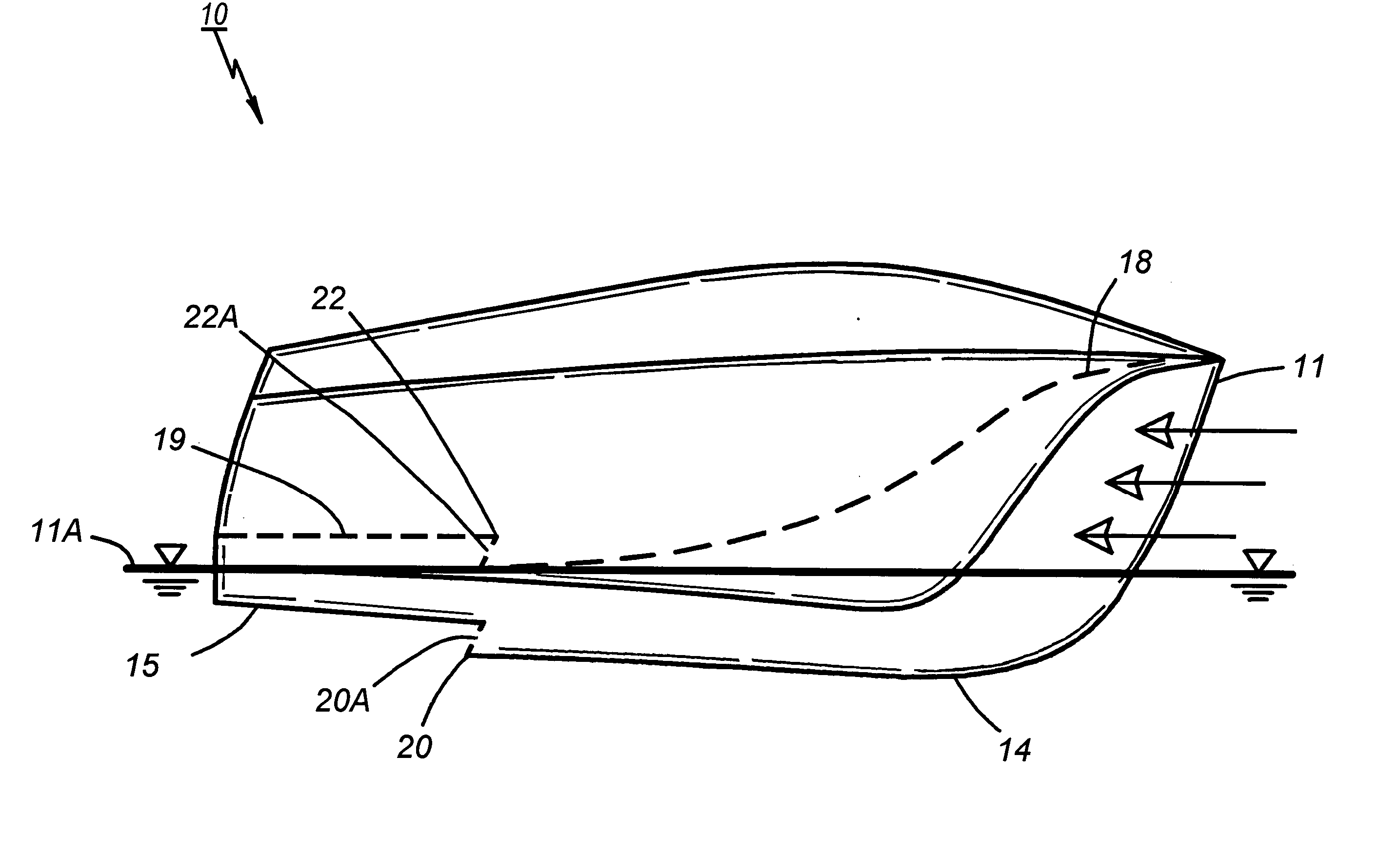
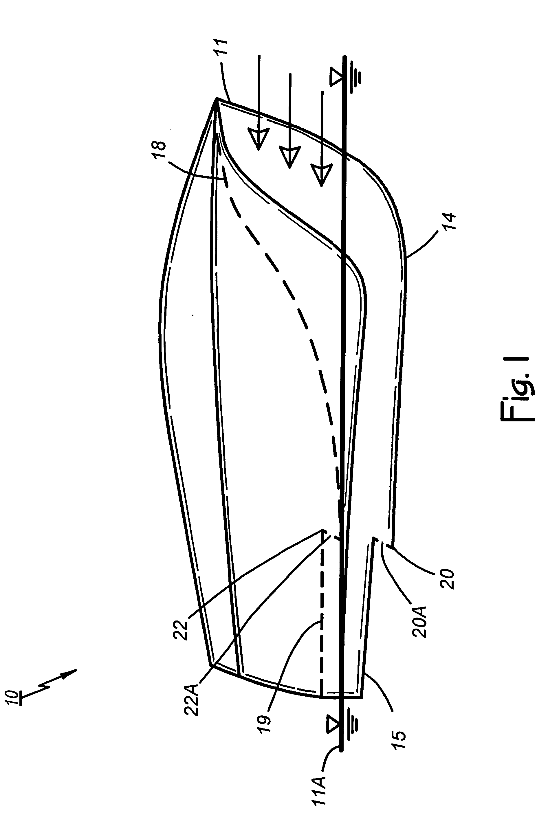
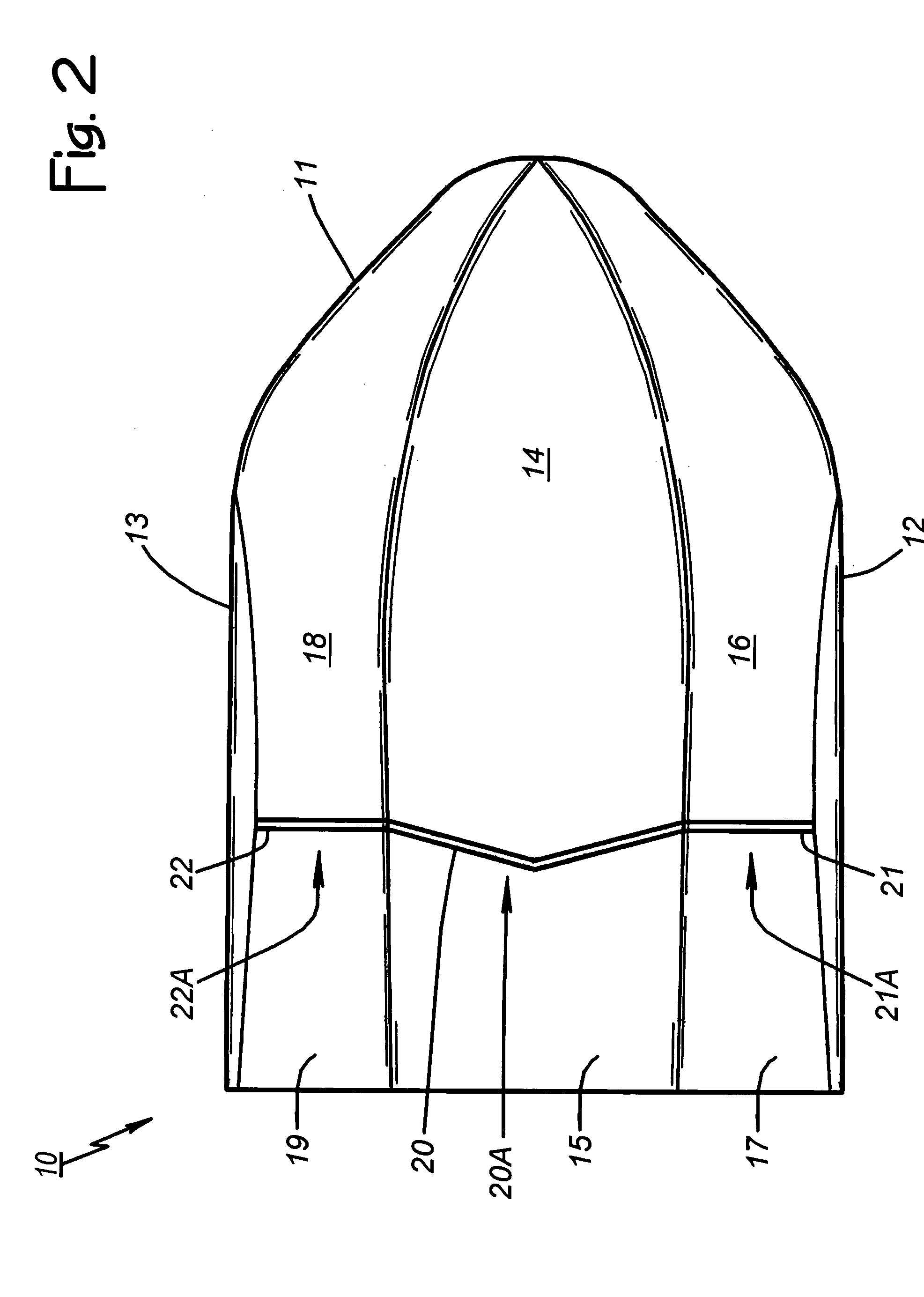
[0020]FIGS. 1-4 of the drawings show various aspects of a powered watercraft 10 constructed according to the invention. Although the invention applies to other than M-shaped boat hulls, the watercraft 10 includes an M-shaped boat hull 11 having a port side 12 (FIGS. 2 and 3) and a starboard side 13 (FIGS. 1-4). The hull 11 includes a central displacement body 14 having a planing surface 15 (FIGS. 1-4), a port channel ceiling 16 having a planing surface 17, and a starboard channel ceiling 18 having a planing surface 19. FIGS. I and 4 include the static water line 11A and three arrows depicting the flow of air when the watercraft 10 is under way. Additional details of the M-shaped boat hull aspects of the watercraft 10 may be had by reference to U.S. Pat. Nos. 6,250,245; 6,314,903; and 6,526,903.

[0021] In line with the major aspect of the invention, the watercraft 10 includes a first vertical step 20 (FIGS. 1-4) in the planing surface 15 of the central displacement body 14. The displ...


PUM


Abstract

A watercraft includes at least one hull having at least one planing surface, at least one vertical step in the planing surface, and an onboard propulsion engine. An exhaust-venting system is provided for venting exhaust from the onboard propulsion engine at the vertical step in the planing surface while under way in order to introduce gas along the planing surface. The hull of one embodiment takes the form of an M-shaped boat hull. The invention also applies to any of various other watercraft hulls, including watercraft with multiple hulls such that each of the multiple hulls includes one or more planing surfaces with one or more vertical steps at which exhaust is vented.

Description

BACKGROUND OF THE INVENTION [0001] 1. Technical Field [0002] This invention relates generally to powered watercraft, and more particularly to a high speed powered watercraft having one or more hulls with one or more planing surfaces. [0003] 2. Description of Related Art [0004] Watercraft with one or more M-shaped boat hulls as described in U.S. Pat. Nos. 6,250,245 and 6,314,903 overcome certain bow wave concerns. They capture and channel the bow wave in order to suppress it. In sea trials of a boat embodying such a hull, the act of increasing power to test the advantages of the air planing cushion at higher boat speeds led to the discovery of unexpected high speed characteristics. Powered watercraft with one or more M-shaped boat hulls as described in U.S. Pat. No. 6,526,903 enhance some of the unexpected high speed characteristics of M-shaped boat hulls. They inject exhaust and / or surplus compressed air from main propulsion engines into the planing channels. Significant performance...

Claims


Application Information

Patent Timeline
Patent Type & Authority Applications(United States)
IPC IPC(8): B63B1/38
CPCY02T70/122B63B1/38Y02T70/10
Inventor ROBINSON, CHARLES W.BURNS, WILLIAM F. III
Owner M SHIP
Why Eureka
Try Eureka