While drilling system and method

a drilling system and drilling method technology, applied in the field of downhole tools, can solve the problems of wd tools being vulnerable to leakage, unable to meet the needs of drilling, and failing to seal the orifice, etc., and achieve the effect of ensuring the integrity of the drilling system and ensuring the integrity of the drilling process

Inactive Publication Date: 2005-01-27
SCHLUMBERGER TECH CORP
View PDF32 Cites 41 Cited by
  • Summary
  • Abstract
  • Description
  • Claims
  • Application Information

AI Technical Summary

Benefits of technology

[0022] The signal and sensor assemblies are preferably provided with one of legacy ceramics, silicon on insulator, multichip modules, field programmable gate array, and combinations thereof. The system may also be provided with a control system including a controller, a processor, a data acquisition module, a transmitter, a receiver, and / or a communication circuit. The sensors may include a transmitter, a receiver, a gauge, and / or a power source. The power source may be chargeable by the while drilling tool. The system may also be provided with a locking mechanism adapted to orient the while drilling tool in the drill collar.
[0023] The system preferably includes continuous direction and inclination capabilities. It is also preferable that the system take continuous measurements in real time and / or performs in high temperature and pressure conditions.

Problems solved by technology

At least some such WD tools may be vulnerable to leakage, seal failure about orifices extending through the drill collar and / or otherwise lack reliability or performance capabilities in a variety of wellbore environments.
The risk of leakage and / or damage may increase in situations where ports extend through the drill collars and into the WD system.
The downhole drilling of wellbores, such as oil wells, involves extreme operating conditions, such as high temperatures, high pressure and rigorous physical impact.
The environment encountered by downhole oil exploration tools can be very severe.
Perhaps the most challenging of all conditions is to design electronics that can reliably operate in high temperature environments.
However, no known commercial MWD tools that are capable of operating above 175 degrees C. for extended periods of time offer desirable operational features, such as real-time gamma ray, retrievability and resetability, as well as vibration detection.
By way of example, one downhole tool has been rated at 180 degrees C. with survivability to 200 degrees C., but lacks continuous inclination and fishability.
The reliability of such a tool has not yet been verified as operational in wells exceeding 170 degrees C. Another tool is rated to 200 degrees C., but it lacks gamma ray, continuous inclination, annular pressure and fishability, and is purported to suffer from poor reliability and low up-hole communication rate.
Electronic components are considered one of the major hurdles to high temperature MWD tools as there are only a few 200 degrees C. components commercially available.
While such attempts offer exciting prospects for the long term, products remain unavailable for commercial processes.
Individual components have yet to be developed, and pose significant costs.

Method used


Image

  • While drilling system and method
  • While drilling system and method
  • While drilling system and method

Examples


Embodiment Construction

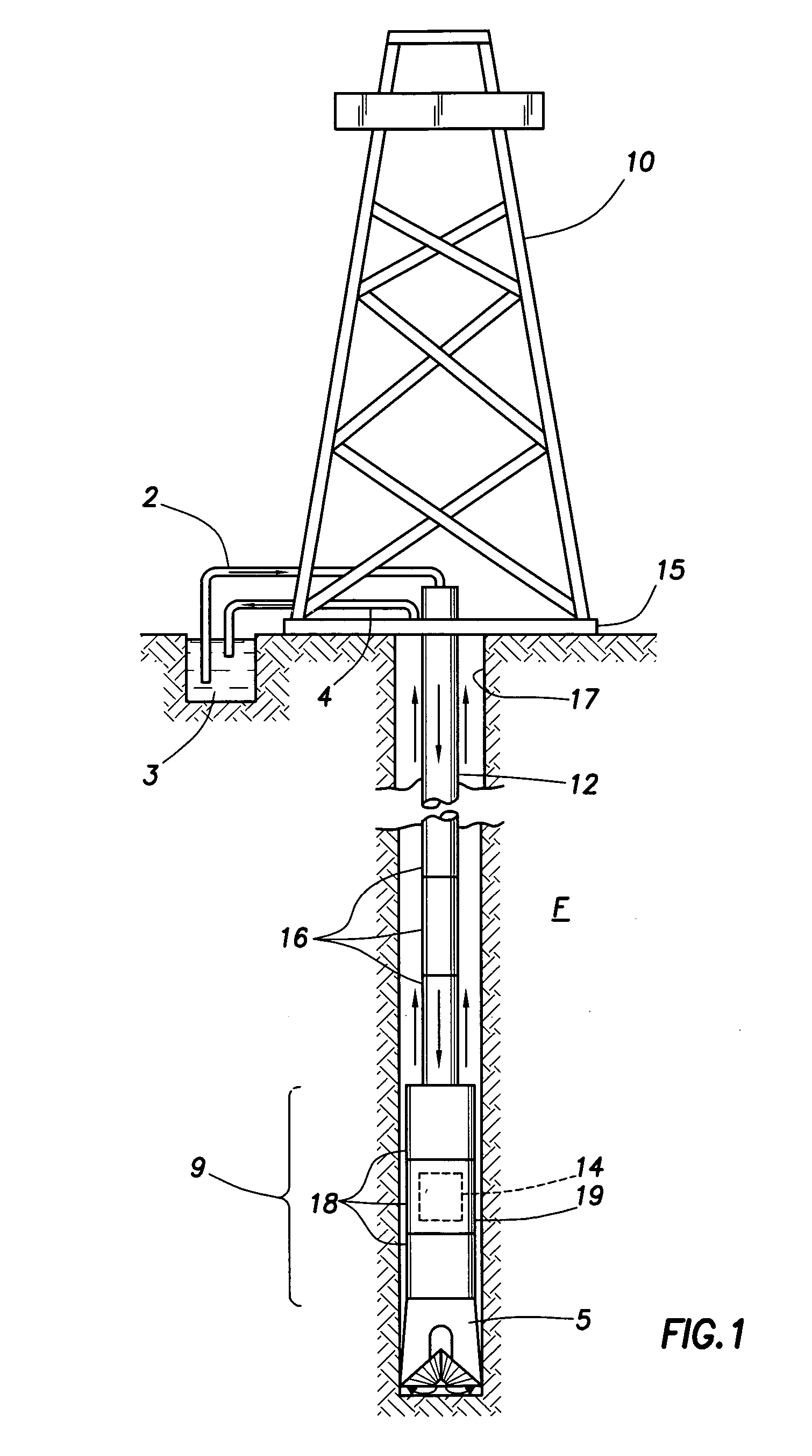
[0034]FIG. 1 is a schematic diagram of a drilling rig 10 and a drill string 12. The drilling rig is mounted on the rig floor 15 and is connected to and supports the drill string through an intricate system of cables and pulleys (not shown). The drill string is suspended from the rig 10 and into a wellbore 17 penetrating a formation F. The drill string includes drill pipes 16 (three are shown in FIG. 1), a bottom hole assembly (BHA) 9 and a drill bit 5 at a lower end thereof. Typically, only a portion of the weight of the drill string is supported at any one time by the formation. The rest is typically kept in suspension by the drilling rig, the cables and pulleys and other supporting components. Drilling of the wellbore commences when the bit is made to turn by various means, either by turning the rig floor rotary table (not shown), or by a drilling motor (not shown) connected between the drill bit and the rest of the drill string.

[0035] During the drilling operation a special flui...


PUM


Abstract

A while drilling system and method for determining annular pressure while drilling is provided. The system is positioned in a drilling tool suspended from a drilling rig via a drill string. The system includes at least one drill collar, a while drilling tool and at least one external sensor. The drill collar has a tubular sidewall defining a passage therein for the flow of drilling mud therethrough. The while drilling tool is supported in the passage of the at least one drill collar and selectively retrievable therefrom. The external sensor is positioned in the sidewall of the drill collar and isolated from the passage. The sensor is exposed to the wellbore for measurement thereof and adapted to wirelessly communicate with the while drilling tool. The system is preferably adapted for use in high temperature and pressure environments.

Description

CROSS REFERENCE TO RELATED APPLICATIONS [0001] This application claims priority to U.S. Provisional Application Ser. No. 60 / 481143 filed on Jul. 25, 2003.BACKGROUND OF INVENTION [0002] 1. Field of the Invention [0003] The present invention relates generally to downhole tools used in performing wellbore operations. More specifically, the present invention relates to techniques for determining downhole parameters via a retrievable downhole while-drilling tool. [0004] 2. Background of the Related Art [0005] The harvesting of hydrocarbons from subterranean formations involves the drilling of wellbores into the earth. To create the wellbore, a downhole drilling tool is suspended from a drilling rig and advanced into the earth via a drill string. During the drilling operation, it is desirable to obtain information about the downhole conditions. Such information is useful, for example, in locating desirable formations, preventing potential problems and improving the drilling operation. [00...

Claims


Application Information

Patent Timeline
Patent Type & Authority Applications(United States)
IPC IPC(8): E21B47/06E21B47/01E21B47/12
CPCE21B47/00G01V11/002E21B47/01E21B47/06E21B47/12
Inventor MAYES, JAMES C.
Owner SCHLUMBERGER TECH CORP
Why Eureka
Try Eureka