Supercharge Your Innovation With Domain-Expert AI Agents!

Apparatus for treatment of contaminated liquids

a technology for contaminated liquids and apparatuses, applied in water/sludge/sewage treatment, centrifugal force sediment separation, sedimentation settling tanks, etc., can solve problems such as affecting the effectiveness of the method over prolonged periods of time, and affecting the effect of the method

Inactive Publication Date: 2005-01-27
QED OCCTECH
View PDF14 Cites 4 Cited by
  • Summary
  • Abstract
  • Description
  • Claims
  • Application Information

AI Technical Summary

Benefits of technology

[0019] wherein, in use, the clarified liquid is reintroduced in a manner so as to cause a downward circular flow to scour out the frusto-conical portion and the conical portion of the base portion and assist in removing heavy contaminants that accumulate adjacent the bottom outlet of the treatment vessel.
[0023] wherein, in use, the clarified liquid is reintroduced in a manner so as to cause a downward circular flow to scour out the frusto-conical portion and the conical portion of the base portion and assist in removing the heavy contaminants that accumulate at a bottom outlet of the treatment vessel.

Problems solved by technology

A problem with existing treatment vessels used in separator systems is that the heaviest contaminants are directed downward toward the apex of the conical bottom of the treatment vessel and can build up a plug which does not flow out of the treatment vessel as desired.
However, it has been found that the effectiveness of the method over prolonged periods of time can sometimes be compromised by the formation of “rat-holes” within the settling sediment, since upon its mechanical removal the sediment adheres to the walls of the conical portion.
Further, access to the bottom portion of the treatment vessel for maintenance and cleaning, in the eventuality of “rat-hole” formation can sometimes be very difficult.

Method used


Image

  • Apparatus for treatment of contaminated liquids
  • Apparatus for treatment of contaminated liquids
  • Apparatus for treatment of contaminated liquids

Examples


Embodiment Construction

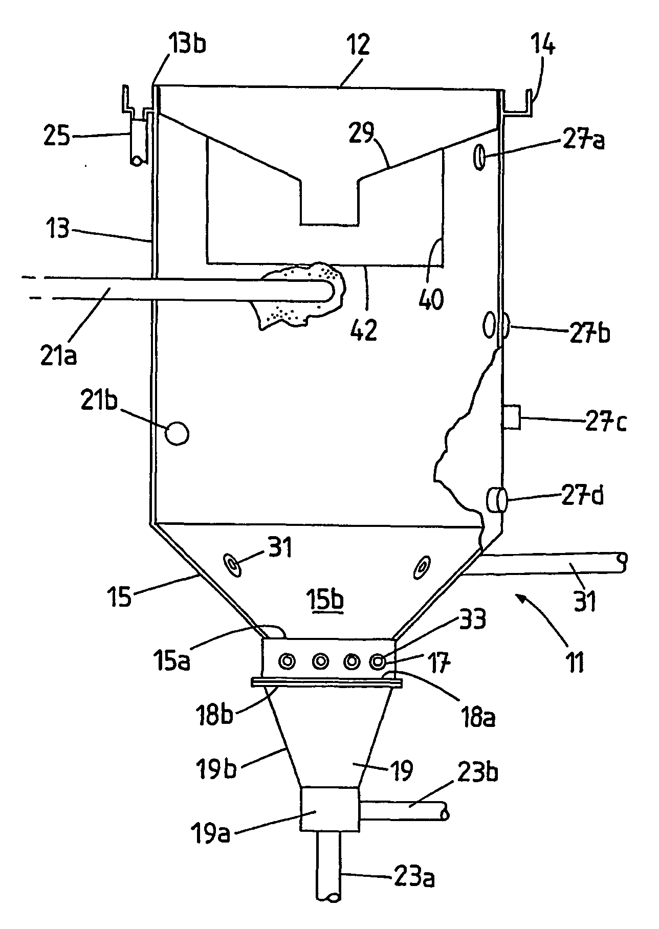
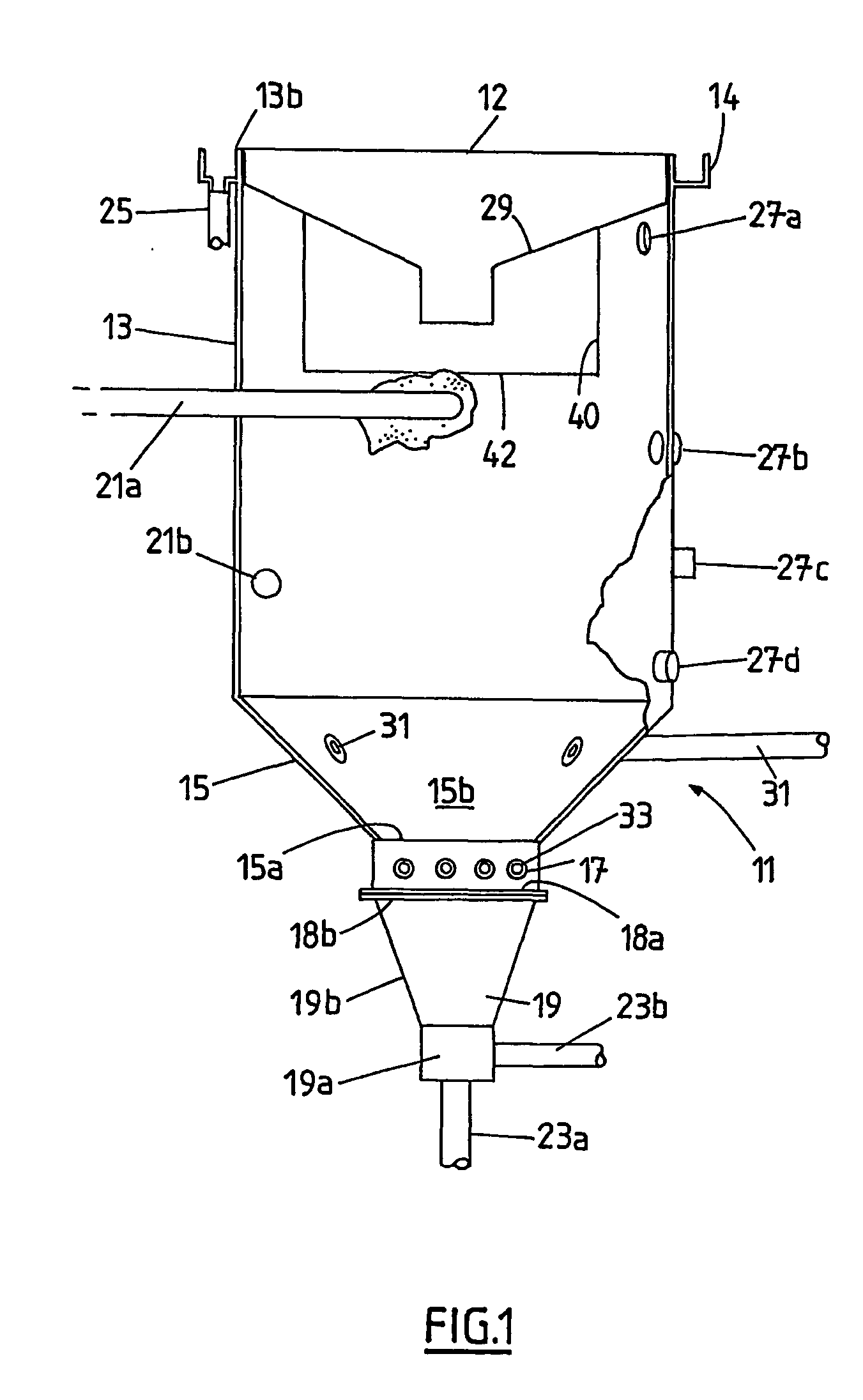
[0027] Referring to the Figures, wherein like numerals and symbols refer to like parts throughout, there is shown a treatment vessel 11. The first and second aspects of the present invention are directed towards a separator system using one or more treatment vessels 11.

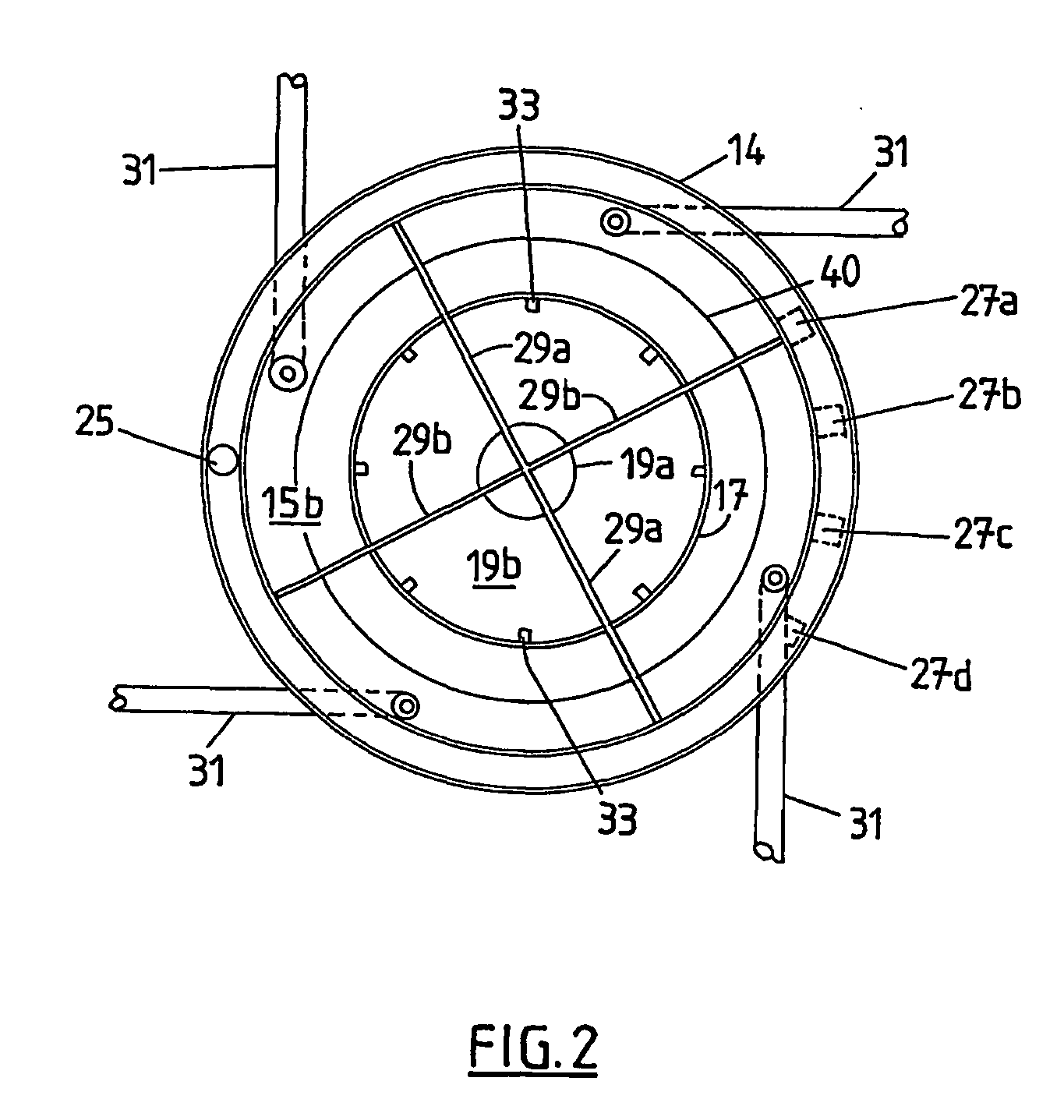
[0028] The treatment vessel 11 comprises a right circular first cylindrical portion 13 having a frusto-conical portion 15 at a lower end thereof, and a right circular second cylindrical portion 17 having a conical portion 19 at a lower end thereof.

[0029] The frusto-conical portion 15 has an apex 15a lower than the side 15b thereof. The second cylindrical portion 17 is integral with the apex 15a, the diameter of the second cylindrical portion 17 being coincident with the diameter of the apex 15a. The conical portion 19 has an apex 19a lower than the side 19b thereof.

[0030] The height of the first cylindrical portion 13 is preferably no more than one and a half times the diameter of the first cylindrical portion 13. ...


PUM

PropertyMeasurementUnit
Angleaaaaaaaaaa
Angleaaaaaaaaaa
Fractionaaaaaaaaaa

Abstract

A treatment vessel for separating contaminants from a base liquid is provided. The vessel comprises a first cylindrical portion, a frusto-conical portion, a second cylindrical portion and a conical portion, the conical portion having a bottom outlet arranged to discharge heavy contaminants from the vessel. Over time, the heavy contaminants settle on the sides of the conical and frusto-conical portions. In order to remove the settled contaminants, the vessel is provided with at least one clarified liquid inlet disposed at or proximate to the frusto-conical portion. The clarified liquid is sourced from either the treatment vessel itself, or another treatment vessel in the same system. The clarified liquid is reintroduced into the vessel in a manner so as to cause a downward circular flow to scour out the frusto-conical portion and the conical portion so as to assist in removal of heavy contaminants that settle on the sides thereof.

Description

FIELD OF THE INVENTION [0001] The present invention relates to an apparatus for treatment of contaminated liquids particularly, but not exclusively, treatment of industrial, agricultural and municipal effluent. BACKGROUND OF THE INVENTION [0002] Vessels for separating contaminants from liquids are well known in the art and are generally in the form of a cylindrical tank with a conical bottom, where the apex of the conical bottom is lower than the outer side thereof. [0003] Inlets may be positioned so as to produce a spiral flow of the liquid in the vessel and outlets may be positioned at the bottom, top and sides of the vessel to enable the drawing off of various fractions of the separated liquid stream, depending on its relative specific gravity. [0004] For the purposes of this specification, a vessel or vessels of aforementioned type will be hereinafter referred to as a “treatment vessel” or “treatment vessels”. [0005] The inlet of a treatment vessel is typically situated at the o...

Claims


Application Information

Patent Timeline
IPC IPC(8): B01D21/00
CPCB01D21/10B01D21/2411B01D21/2416B01D21/26B01D21/2444B01D21/245B01D21/2427B01D21/0006
Inventor WALKER, WILLIAM
Owner QED OCCTECH
Features
  • R&D
  • Intellectual Property
  • Life Sciences
  • Materials
  • Tech Scout
  • Unparalleled Data Quality
  • Higher Quality Content
  • 60% Fewer Hallucinations
Learn More