Personnel heating assembly

Active Publication Date: 2005-01-27
GRI ALLESET INC
View PDF21 Cites 63 Cited by
  • Summary
  • Abstract
  • Description
  • Claims
  • Application Information

AI Technical Summary

Benefits of technology

[0010] A disposable overcover for said electric blanket is impervious to liquid and encases the blanket, including electrical connectors and conductors, to avoid contamination of the blanket and thereby rendering the blanket usable for other patients merely by replacement of the overcover.
[0011] Alternativel

Problems solved by technology

Alternating current (AC) power sources or DC power sources with significant pulsations generate unacceptable electromagnetic waves and are accordingly not

Method used


Image

  • Personnel heating assembly
  • Personnel heating assembly
  • Personnel heating assembly

Examples


Embodiment Construction

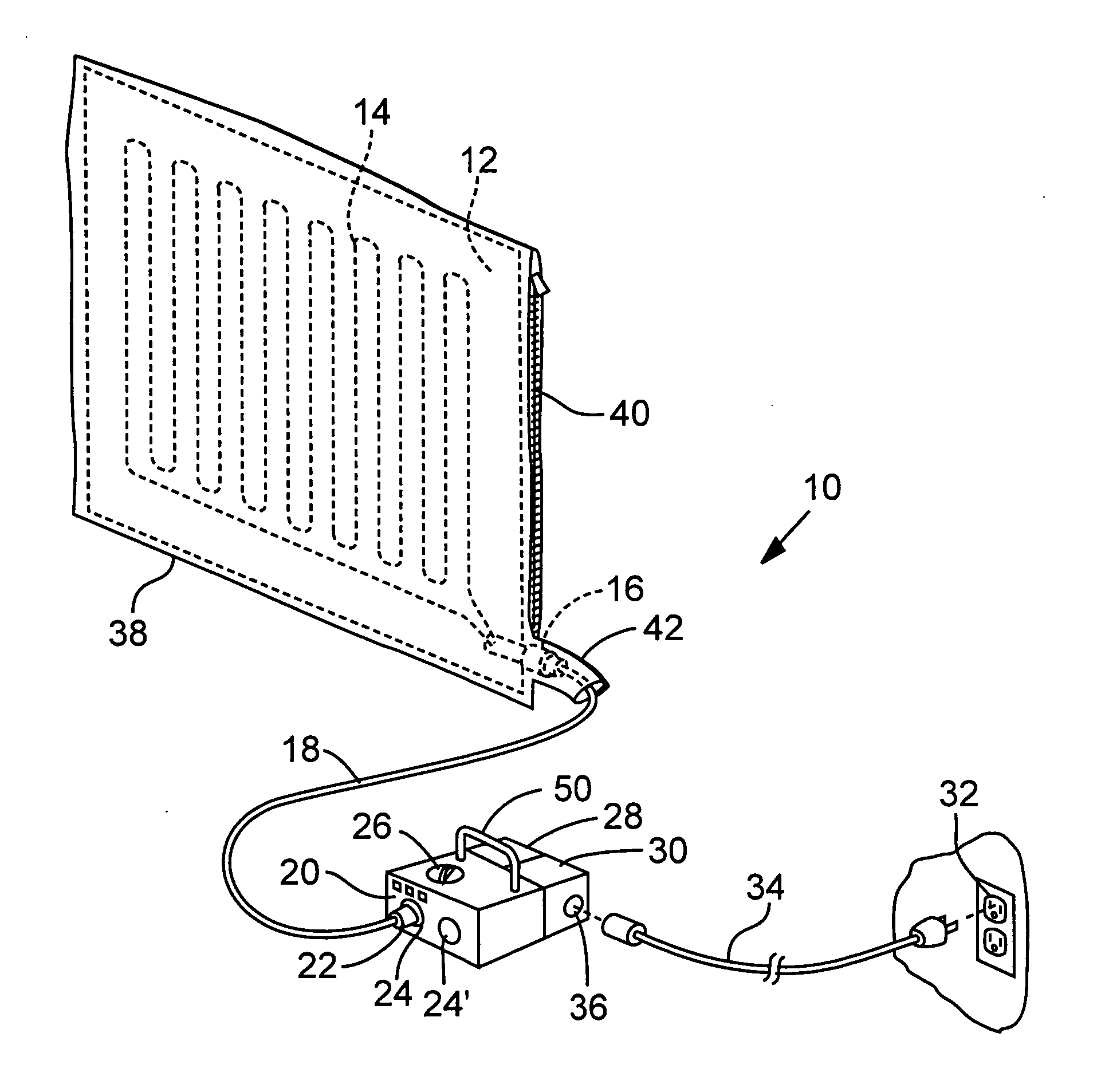
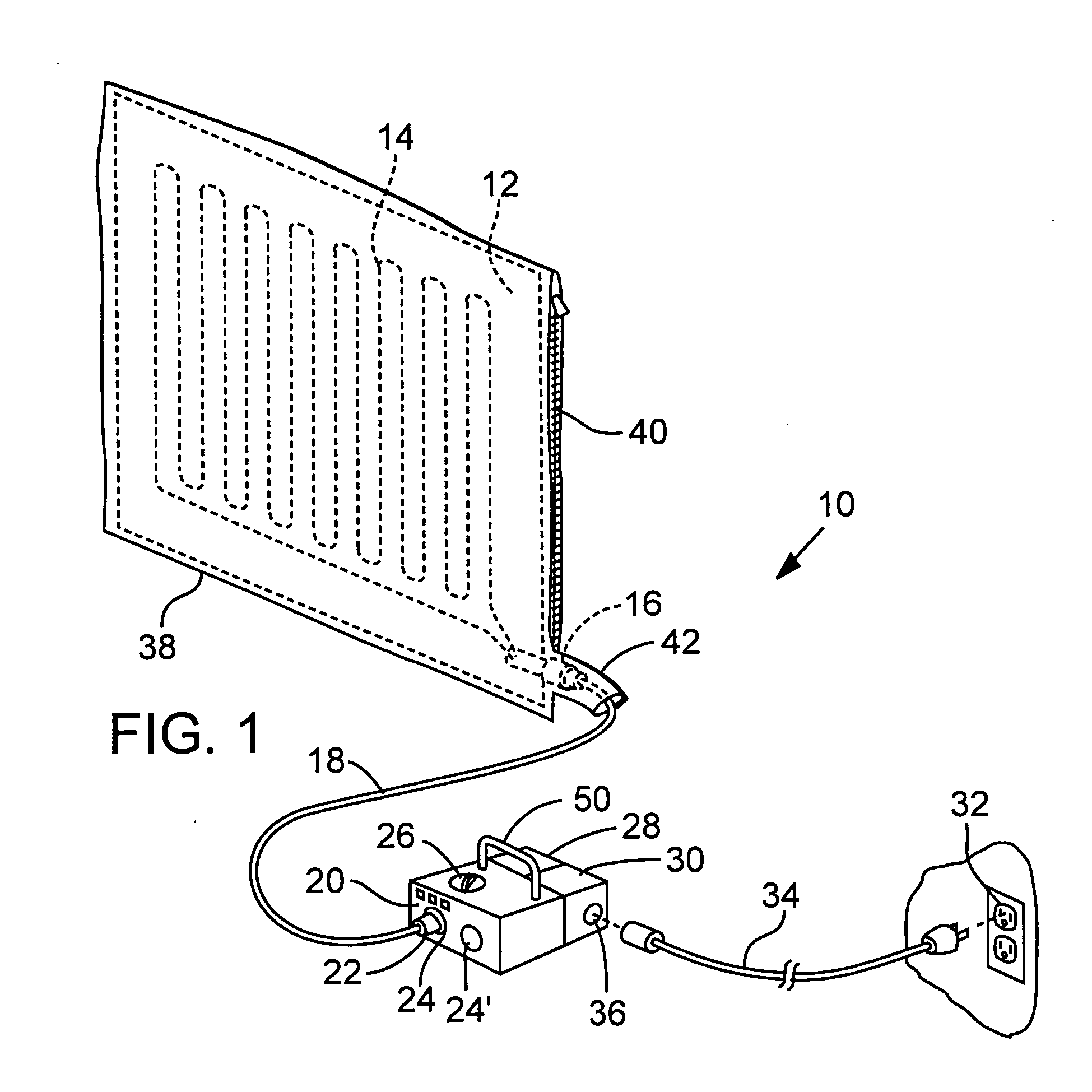
[0023]FIG. 1 illustrates an electric personnel warming assembly 10 in accordance with the present invention. The assembly includes a multi-layered blanket or cover portion 12 having direct current (DC) wiring circuit 14 affixed to an insulated layer within the blanket (not shown but see commonly owned U.S. Pat. No. 5,986,243 incorporated herein by reference). The blanket is desirably constructed of pliable cloth-like layers that include the desired insulation, heat reflection and heat conductive properties to ideally promote inwardly directed heat conveyance to a patient covered by the blanket. A connector 16 and wire conductor 18 connect the heating circuitry 14 to a control apparatus 20 via a second connector 22 and plug in 24.

[0024] The control unit or apparatus 20 includes multiple features. A control dial or pad 26 is usable by an operator to increase and decrease the energy input to circuitry 14 for increasing and decreasing heat conveyance to the blanket, and alternatively o...


PUM


Abstract

A heating assembly, including a blanket portion and a control apparatus for electrically heating the blanket portion. The control apparatus generates direct current power of desired wave form to enable the assembly to be used for warming patients without interference of medical equipment as may be used in the process of a surgery. Alternate power sources include battery power and alternating current power transformed by a transformer into direct current power.

Description

RELATED APPLICATION [0001] This application is a non-provisional application claiming benefit under 35 U.S.C. § 120 of U.S. Provisional Application No. 60 / 401,006, filed Aug. 5, 2002.BACKGROUND OF THE INVENTION [0002] 1. Field of the Invention [0003] This invention relates to an electric blanket that operates on DC power and can accordingly be battery operated to enable users to operate the heating elements of the blanket where AC power is not available, e.g. golf cart or medical EMT use, or otherwise where AC power is not desirable, e.g., for warming patients in an environment where power cords or electromagnetic waves from alternating current sources may be detrimental. [0004] 2. Background Information [0005] Battery powered electric blankets are not new, as illustrated in the commonly owned U.S. Pat. No. 5,986,243, the disclosure of which is incorporated herein by reference. Whereas the electric blanket of the '243 patent was primarily targeted as a stadium blanket, a secondary u...

Claims


Application Information

Patent Timeline
IPC IPC(8): H05B1/02H05B3/34
CPCH05B1/0272H05B2203/003H05B3/342
Inventor CAMPF, MELVIN F.THORNE, JIMHOMOYOUN, HABIBFIELDS, R. WAYNE
Owner GRI ALLESET INC
Why Eureka
Try Eureka