Efficiency improved voltage converter

a voltage converter and efficiency improvement technology, applied in the field of voltage converter efficiency improvement, can solve the problems of buck-boost converters that do not have high conversion efficiency, buck-boost converters b>, gradual decay of battery voltage with its operational time or sudden drop, etc., and achieve the effect of improving efficiency

Inactive Publication Date: 2005-01-27
RICHTEK TECH
View PDF2 Cites 128 Cited by
  • Summary
  • Abstract
  • Description
  • Claims
  • Application Information

AI Technical Summary

Benefits of technology

[0008] One object of the present invention is to provide a voltage converter in which the efficiency is improved by a combination of linear mode and switch mode converters. In a voltage converter, according to the present invention, a boost converter is connected between a supply voltage provided by one or more batteries and a first output, a buck converter is connected between the supply voltage and a second output, and a low dropout (LDO) regulator is connected between the first output and the second output. The boost converter boosts up the supply voltage to generate a first output voltage at the first output, and the buck converter bucks down the supply voltage to generate a second output voltage at the second output. When the supply voltage is lower than a threshold, the LDO regulator converts the first output voltage to a third voltage at the second output. A shutdown circuit is further included in the buck converter to turn off the buck converter to prevent reverse current to flow toward to the battery.

Problems solved by technology

However, the battery voltage will be gradually decayed with its operational time or suddenly dropped down resulted from instant increasing of load current flowing through the internal resistor of the battery.
However, a buck-boost converter does not have high conversion efficiency, and the two energy-storing elements, inductors L2 and L3, bring the buck-boost converter 24 to high cost and large size.

Method used


Image

  • Efficiency improved voltage converter
  • Efficiency improved voltage converter
  • Efficiency improved voltage converter

Examples


Embodiment Construction

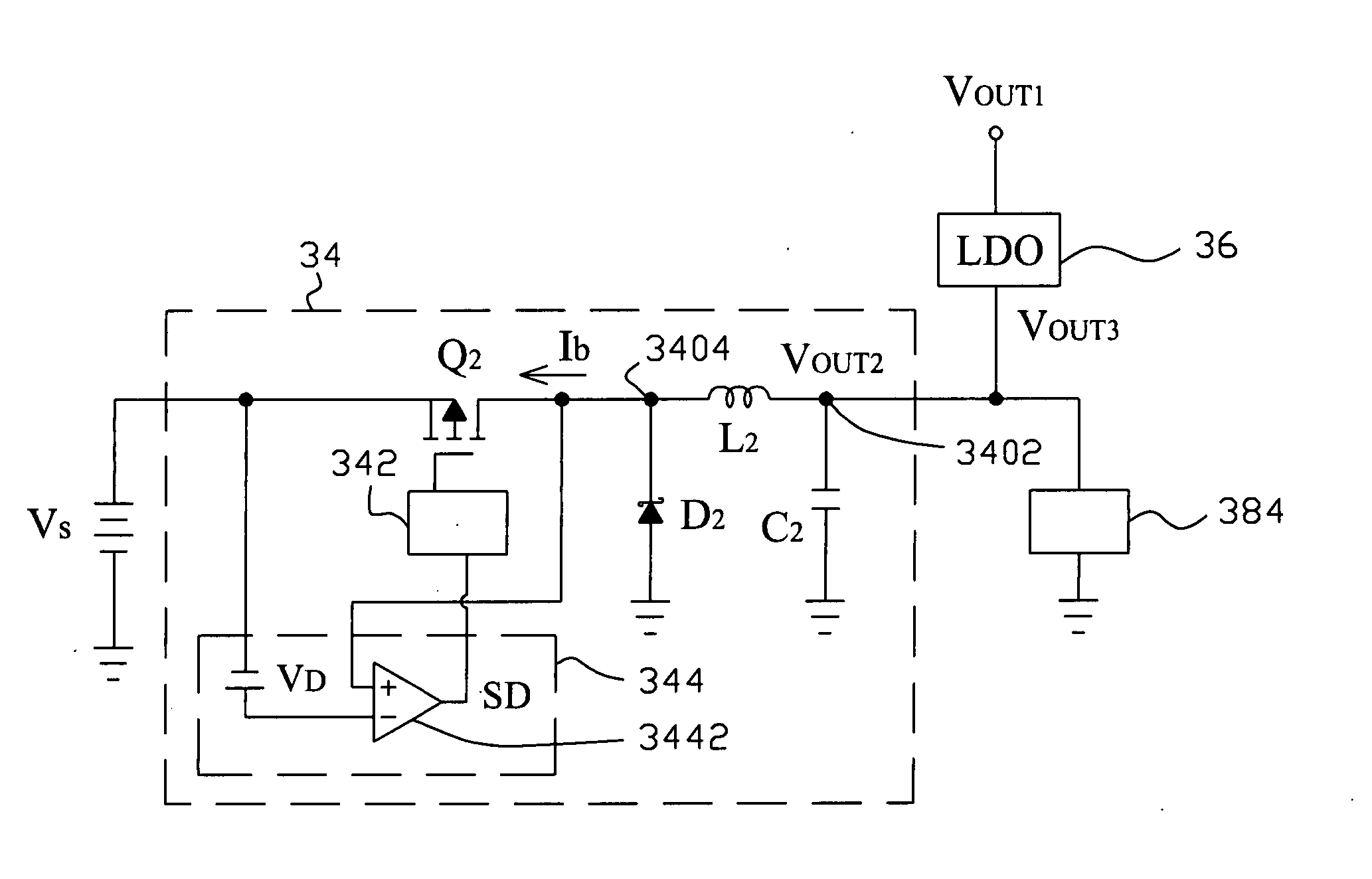
[0016]FIG. 3 shows an embodiment according to the present invention, in which linear mode and switch mode converters are combined together to improve the efficiency thereof. A voltage converter 30 comprises a boost converter 32 connected with a supply voltage VS to boost up the supply voltage VS to generate an output voltage VOUT1, at its output 3202 to supply for a load 382 connected to the output 3202, a buck converter 34 connected with the supply voltage VS to buck down the supply voltage VS to generate another output voltage VOUT2 at its output 3402 to supply for another load 384 connected to the output 3402, and an LDO regulator 36 connected between the outputs 3202 and 3402 to convert the output voltage VOUT1 to yet another output voltage VOUT3 at the output 3402 connected with the load 384 when the output voltage VOUT2 is lower than a threshold. The boost converter 32 comprises an inductor L1 connected between the supply voltage VS and a node 3204, a diode D1 connected betwee...


PUM


Abstract

A voltage converter improves the efficiency thereof by connecting a boost converter and an LDO regulator with a buck converter in parallel. The boost converter boosts up a supply voltage to generate a first output voltage at a first output, and the buck converter bucks down the supply voltage to generate a second output voltage at a second output. When the second output voltage is lower than a threshold, the LDO regulator converts the first output voltage to a third voltage at said second output.

Description

FIELD OF THE INVENTION [0001] The present invention relates generally to a voltage converter and more particularly, to the efficiency improvement of a voltage converter. BACKGROUND OF THE INVENTION [0002] Battery is widely used for the power source in portable electronic products. However, the battery voltage will be gradually decayed with its operational time or suddenly dropped down resulted from instant increasing of load current flowing through the internal resistor of the battery. For a battery voltage will be out of a desired range, it is generally employed buck-boost converter or two-stage, i.e., boost-then-buck, voltage converter in order to maintain a stable output voltage for power supply to a load. [0003]FIG. 1 shows a conventional two-stage voltage converter 10 that includes a boost converter 12 connected in series with a buck converter 14. The boost converter 12 is connected between a supply voltage VS provided by one or more batteries and an output 1202 to boost up the...

Claims


Application Information

Patent Timeline
Patent Type & Authority Applications(United States)
IPC IPC(8): G05F1/575
CPCG05F1/575
Inventor HSU, CHIH-YUAN
Owner RICHTEK TECH
Why Eureka
Try Eureka