Magnetoresistive turbocharger compressor wheel speed sensor

a magnetoresistive turbocharger and compressor wheel technology, which is applied in the direction of machines/engines, mechanical equipment, instruments, etc., can solve the problems of not being able to sense the speed of magnetoresistive sensors, the speed of non-ferromagnetic compressor wheels is not able to be magnetically detected, and the engine performance is less than optimal for open-loop controlled turbochargers. achieve the effect of reducing the pulse ra

Inactive Publication Date: 2005-01-27
HONEYWELL INT INC
View PDF12 Cites 100 Cited by
  • Summary
  • Abstract
  • Description
  • Claims
  • Application Information

AI Technical Summary

Benefits of technology

[0010] According to still another aspect of the present invention, a method of sensing rotation of a non-ferromagnetic compressor wheel of a turbocharger comprises the following: inducing eddy currents in fins of the non-ferromagnetic compressor wheel

Problems solved by technology

However, running a turbocharger too far below its maximum speed results in less than optimal performance of the engine supplied by the open loop controlled turbocharger.
Moreover, many turbocharger warranty claims are caused by over speed conditions, and many of these over speed warranty claims are due to the inability of c

Method used


Image

  • Magnetoresistive turbocharger compressor wheel speed sensor
  • Magnetoresistive turbocharger compressor wheel speed sensor
  • Magnetoresistive turbocharger compressor wheel speed sensor

Examples


Embodiment Construction

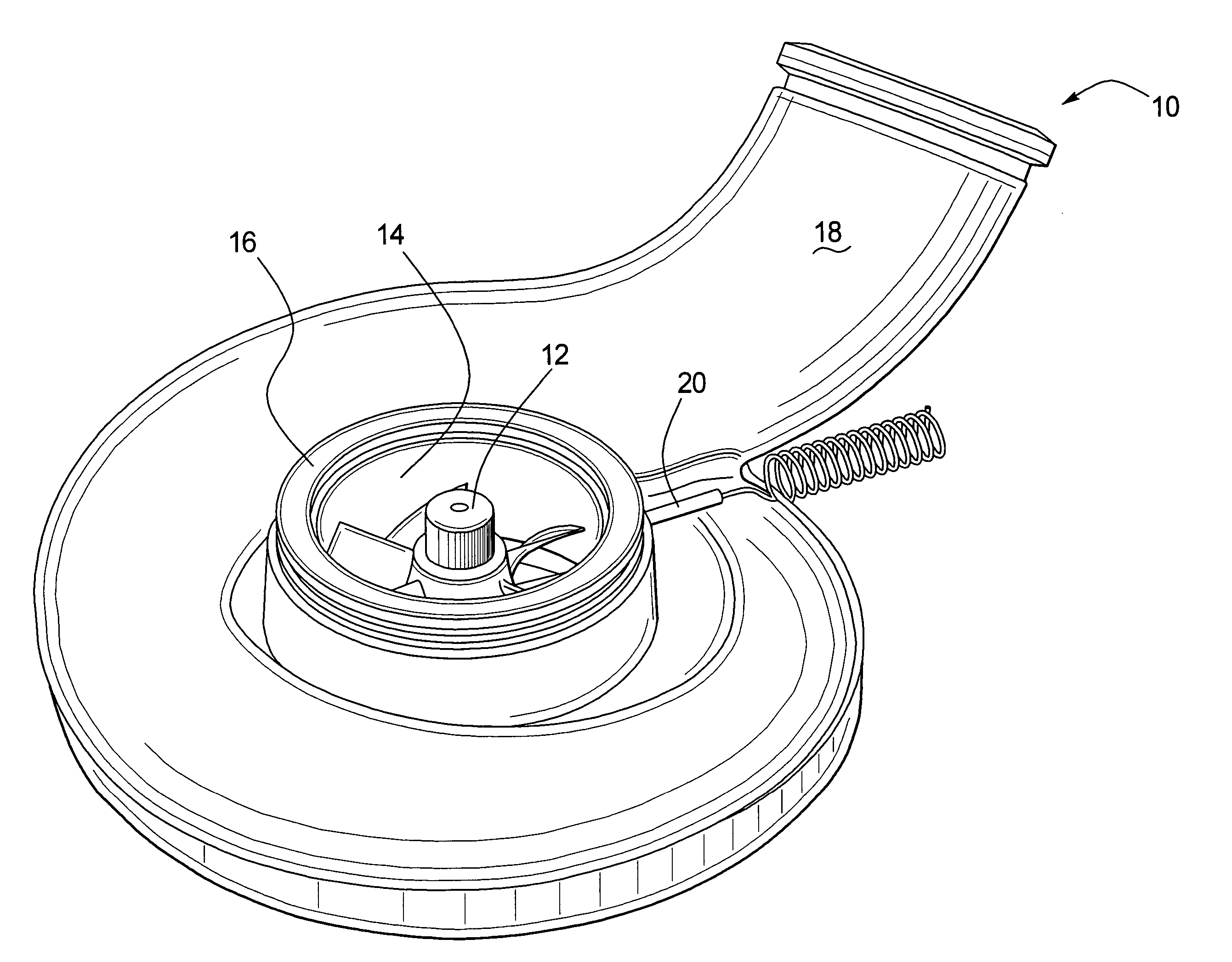
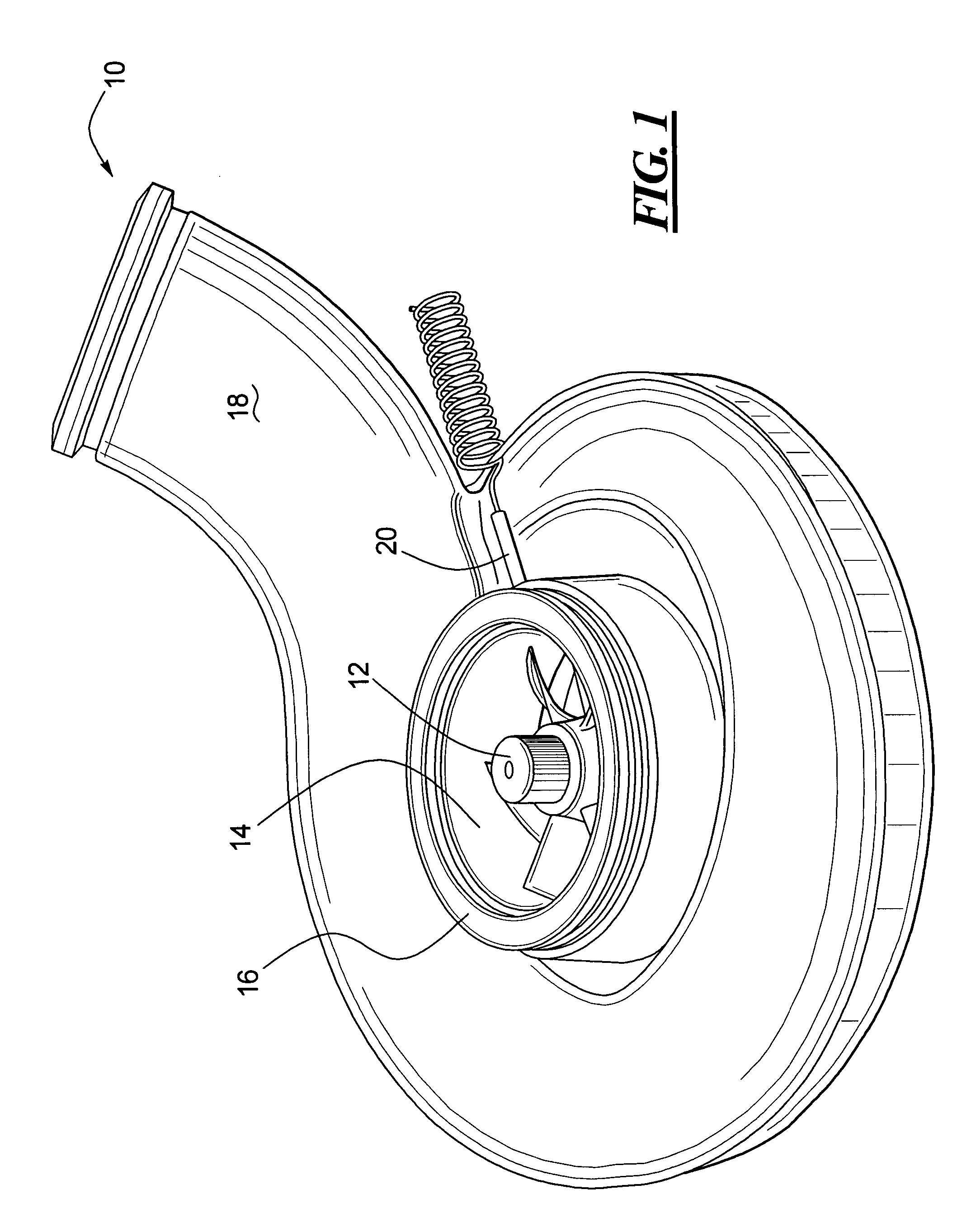
[0021] A compressor section 10 of a turbocharger is shown in FIG. 1 and includes a turbocharger compressor wheel 12 that rotates within a cylindrical chamber 14 formed by a cylindrical wall 16. The turbocharger compressor wheel 12 is typically rotated by a turbine wheel (not shown) and the turbine wheel may be suitably controlled to rotate the turbocharger compressor wheel 12 at a desired speed. Accordingly, the turbocharger compressor wheel 12 draws air into the cylindrical chamber 14 (from above as shown in FIG. 1) and supplies the air under pressure through an outlet 18 to an engine such as a diesel or gasoline engine.

[0022] A magnetoresistive sensor 20 is received in an aperture of the cylindrical wall 16 in order to sense the speed at which the turbocharger compressor wheel 12 rotates within the cylindrical chamber 14.

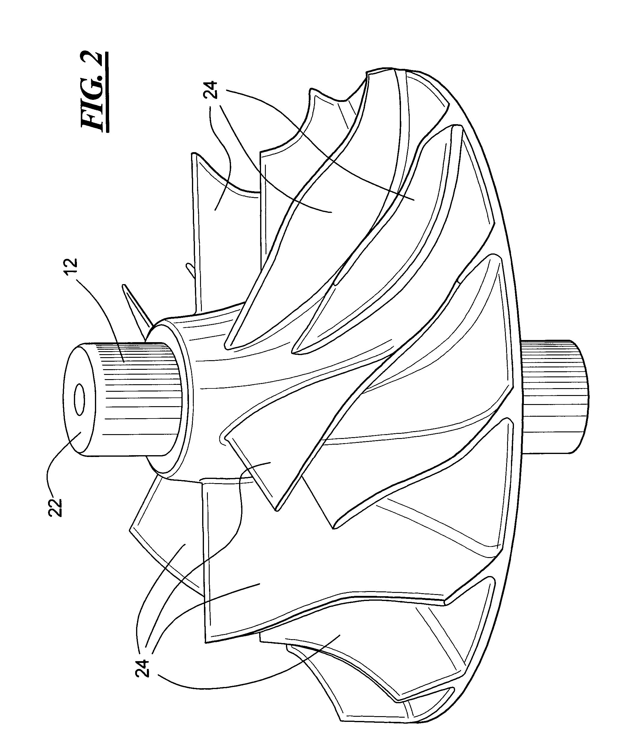
[0023] As shown in FIG. 2, the turbocharger compressor wheel 12 has a shaft 22 and a plurality of fins 24 radiating out from the shaft 22. The turbocharger comp...


PUM


Abstract

A turbocharger includes a cylindrical wall and a non-ferromagnetic compressor wheel within the cylindrical wall. The non-ferromagnetic compressor wheel has fins. A magnetoresistive sensor housing is threaded through the cylindrical wall and houses a permanent magnet and at least one magnetoresistor. The permanent magnet is positioned so as to induce eddy currents on the fins. The permanent magnet magnetically biases the magnetoresistor, and the magnetoresistor senses rotation of the non-ferromagnetic compressor wheel.

Description

TECHNICAL FIELD OF THE INVENTION [0001] The present invention relates to the use of a magnetoresistive sensor to sense the speed of a rotating non-ferromagnetic device such as the wheel of a turbocharger compressor. BACKGROUND OF THE INVENTION [0002] Turbocharging is the force feeding of an engine with air under pressure in order to improve the fuel economy, emissions, and performance of the engine. In a typical turbocharger, an engine's exhaust is used to drive a turbine wheel which in turn drives a compressor wheel through a shaft that interconnects the turbine and compressor wheels. The compressor wheel of the turbocharger draws air into the turbocharger and moves the air by centrifugal force to the outlet of the turbocharger for supply to the engine. [0003] Frequently, a turbocharger is controlled in an open loop manner, meaning that the speed of the compressor wheel is not used to provide feedback in order to control the speed of the compressor wheel. Therefore, in order to avo...

Claims


Application Information

Patent Timeline
IPC IPC(8): F01D17/06F01D21/00G01P3/488G01P3/49
CPCF01D17/06F01D21/003F05D2270/304G01P3/49F05D2220/40G01P3/488
Inventor STOLFUS, JOEL D.BUSCH, NICHOLAS F.
Owner HONEYWELL INT INC
Why Eureka
Try Eureka