
Antenna device

Inactive Publication Date: 2005-01-27
WIRELESS READING SYST
View PDF7 Cites 26 Cited by
  • Summary
  • Abstract
  • Description
  • Claims
  • Application Information

AI Technical Summary

Benefits of technology

[0014] A second object of the invention is to provide an antenna device, a remote reading device, a method and an application as mentioned in the introduction, which provide a high level of reliability, good broadband characteristics, inexpensive production and installation costs, utilisation of already existing equipment and minimal space requirements.

Problems solved by technology

When a radio-based reading unit is placed inside such a cabinet, a problem is to provide a suitable antenna for the reading unit.
A solution of this kind will result in altered radiation characteristics for the antenna and difficult radio communication conditions if the remote reading unit is located in a partially tight, earthed installation cabinet such as a metal fuse box.
The solution cannot be seen to be suitable for using the power supply line as an antenna for wireless radio transmission over long distances.
The necessity of a separate wire antenna apparently does not make this solution suitable for use with a radio transmitter located in a metal cabinet.

Method used


Image

  • Antenna device
  • Antenna device
  • Antenna device

Examples


first embodiment

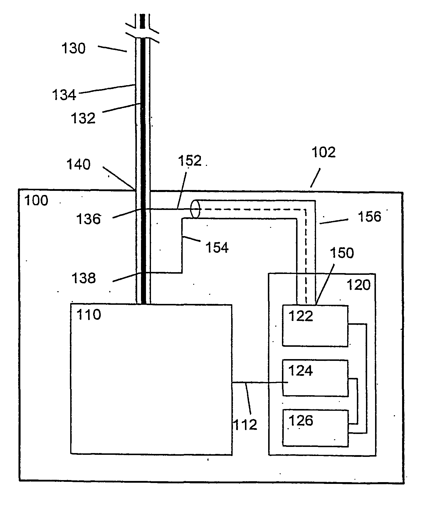
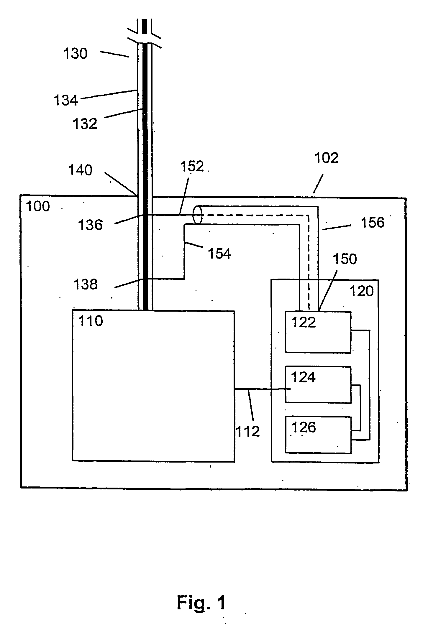
[0024]FIG. 1 illustrates system components in an installation cabinet in which is included an antenna device according to the invention.

[0025] An installation cabinet 100, such as a fuse box, is composed of a metallic housing, where a number of alternating current supply lines are passed in and out through openings in the cabinet. A line of this kind is indicated by 130. The line 130 is schematically indicated as a single conductor with a conducting core 132 surrounded by an insulation layer 134. In practice the line may be composed of a phase conductor in a multi-conductor cable, such as a cable with two phase conductors and an earth conductor.

[0026] Inside the cabinet 100 the line 130 is passed inter alia to a supply meter 110, which may, e.g., be of a type which measures accumulated energy consumption based on the current supplied through the supply line, and which displays these data as a series of numbers.

[0027] The supply meter is provided with a remote reading device 120. T...

second embodiment

[0038]FIG. 3 illustrates system components in an installation cabinet in which is included an antenna device according to the invention.

[0039] In this embodiment too, the antenna device comprises a signal connection of the antenna output 150 to a section of the supply line inside the installation cabinet 100. In this case, however, the signal connection is a capacitive coupling. This is achieved by the antenna device comprising a first capacitive coupling element 137 for capacitive connection of the first 152 conductor to the section of the supply line and a second capacitive coupling element 139 for capacitive connection of the second conductor 154 to the chassis potential of the installation cabinet 100.

[0040] The capacitive coupling elements may be implemented by means of metallic tape. The first capacitive coupling element may be a metallic tape that envelops the supply line, while the second capacitive coupling element may be a metallic tape arranged in against the wall of the...

third embodiment

[0041]FIG. 4 illustrates system components in an installation cabinet in which is included an antenna device according to the invention.

[0042] In this embodiment too, the antenna device comprises a signal connection of the antenna output 150 to a section of the supply line inside the installation cabinet 100.

[0043] In this case, however, at least a first 230 and a second 330 supply line are passed through openings in the installation cabinet. The signal connection is capacitive, as in the embodiment in FIG. 3. However, this is achieved here by the antenna device comprising [0044] a first capacitive coupling element 237 for capacitive connection of the first conductor 152 to a section of the first supply line 230 inside the installation cabinet 100, [0045] a second capacitive coupling element 337 for capacitive connection of the second conductor 154 to a section of the second supply line 330 inside the installation cabinet 100, and [0046] a third capacitive coupling element 239 for ...


PUM


Abstract

The invention relates to an antenna device for use with a radio transmitter (122) mounted in an electrical installation cabinet (100) such as a fuse box, where at least one electrical supply line (130) is passed through an opening (140) in the installation cabinet (100). The antenna device comprises a signal connection of the radio transmitter's antenna output (150) to a section of the supply line inside the installation cabinet (100). The result of this is that the supply line (130) is employed as a travelling wave antenna for the radio transmitter (122). The invention further relates to a remote reading device in which the device is included, a method for providing an antenna for a radio transmitter in an installation cabinet and an application of a supply line that is passed into or out of the installation cabinet.

Description

FIELD OF THE INVENTION [0001] The present invention relates to radio communication, especially radio communication employed in the field of remote reading of energy consumption meters. [0002] In more specific terms the invention relates to an antenna device for use with a radio transmitter mounted in an electrical installation cabinet such as a fuse box. [0003] The invention also relates to a remote reading device for remote reading of an energy consumption meter to be mounted in such an installation cabinet. [0004] The invention further relates to a method for providing an antenna for a radio transmitter mounted in such an electrical installation cabinet. [0005] The invention finally relates to an application of an electrical supply line passed into or out of an electrical installation cabinet such as a fuse box. BACKGROUND ART [0006] Energy consumption meters, such as supply meters for electrical energy, water or gas were formerly read manually. In recent times a number of remote ...

Claims


Application Information

Patent Timeline
IPC IPC(8): H04B3/60
CPCH04B3/60H04B2203/5441H04B2203/5433
Inventor SAEGROV, ATLE
Owner WIRELESS READING SYST
Learn More