Apparatus and method for measuring characteristics of iptical fibers

a technology of optical fibers and apparatuses, applied in the direction of optical apparatus testing, structural/machine measurement, instruments, etc., can solve the problems of chromatic dispersion (the sum of material dispersion and waveguide dispersion), waveform deterioration, and polarization mode dispersion, etc., to achieve accurate measurement of the characteristics of subject optical fibers

Active Publication Date: 2005-01-27
ANDO ELECTRIC CO LTD +1
View PDF3 Cites 17 Cited by
  • Summary
  • Abstract
  • Description
  • Claims
  • Application Information

AI Technical Summary

Benefits of technology

It is an object of this invention to realize an apparatus and method for measuring characteristics of optical fibers that enable accurate measurement of characteristics of subject optical fibers.

Problems solved by technology

However, since dispersions such as material dispersion, waveguide dispersion, multimode dispersion and polarization mode dispersion exist in optical fibers as transmission media, waveform deterioration due to these dispersions is particularly considered to cause troubles.
In the case where single-mode optical fibers are used, chromatic dispersion (sum of material dispersion and waveguide dispersion) and polarization mode dispersion are problems.
On the other hand, polarization mode dispersion is caused by various elements such as structural defects of the optical fibers themselves, and elliptic deformation of the core, flexure, stress, and twisting due to manufacturing conditions, construction conditions, use environment and the like.
Therefore, it is difficult to compensate polarization mode dispersion using passive components.
However, the apparatus shown in FIGS. 2 and 3 has a problem that it cannot detect the circular polarization component of birefringence within the subject optical fiber 100 simply and directly, as described in J. N. Ross, “Birefringence measurement in optical fibers by polarization-optical time-domain reflectometry,” Applied Optics (U.S.), Optical Society of America (OSA), October 1982, Vol. 21, No. 19, pp.
However, since this value is acquired from many numerical simulations and statistics, the value is not effective for all the subject optical fibers 100 and it is difficult to accurately find polarization mode dispersion, that is, the characteristics of the optical fibers

Method used


Image

  • Apparatus and method for measuring characteristics of iptical fibers
  • Apparatus and method for measuring characteristics of iptical fibers
  • Apparatus and method for measuring characteristics of iptical fibers

Examples


first embodiment

[First Embodiment]

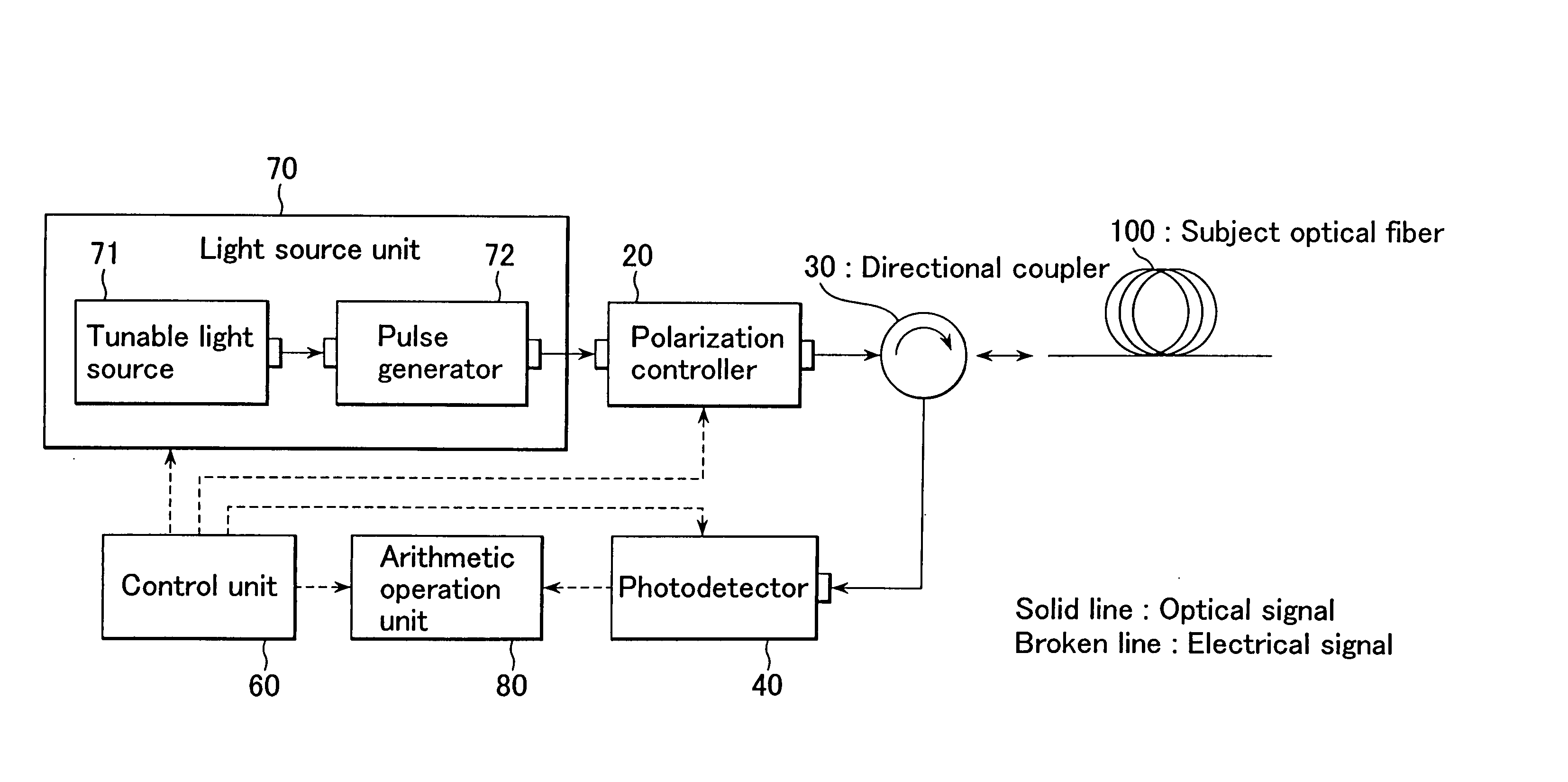
FIGS. 4 and 5 are structural views showing a first embodiment of this invention. The same elements as those shown in FIGS. 2 and 3 are denoted by the same numerals and will not be described further in detail. In FIG. 4, a light source unit 70 is provided instead of the light source unit 10. An arithmetic operation unit 80 is provided instead of the arithmetic operation unit 50.

The light source unit 70 has a tunable light source 71 and a pulse generator 72, and outputs at least three kinds of pulse light having different angular frequencies, for example, three kinds of pulse light having angular frequencies ω1, ω2, ω3 (the angular frequencies (ω1, ω2, ω3 are slightly different from each other at an angular frequency spacing Δω). The tunable light source 71 is a continuous light output unit. It variably controls the angular frequencies ω1, ω2, ω3 and outputs continuous light having the desired angular frequencies ω1, ω2, ω3. The pulse generator 72 converts the cont...

second embodiment

[Second Embodiment]

The embodiment of measuring polarization mode dispersion by the apparatus shown in FIGS. 4 and 5 is described above. Polarization mode dispersion is generated by birefringence in the optical fiber. That is, it is also important to measure the magnitude of birefringence, which is one of the characteristics in the longitudinal direction of the subject optical fiber 100. FIG. 7 is a structural view showing a second embodiment of this invention. In FIG. 7, the same elements as those shown in FIG. 4 are denoted by the same numerals and will not be described further in detail.

In FIG. 7, a birefringence calculating unit 90 is further provided. As the photodetector 40 detects the light intensity at least at three positions z1, z2, z3 (z1, z2, z3 are slightly different from each other at a very small position spacing Δz) in the longitudinal direction of the subject optical fiber 100, the birefringence calculating unit 90 calculates a birefringence vector of back scatter...


PUM

PropertyMeasurementUnit
polarization mode dispersionaaaaaaaaaa
angular frequenciesaaaaaaaaaa
light intensityaaaaaaaaaa

Abstract

An apparatus and method for measuring characteristics of optical fibers that enable accurate measurement of characteristics of optical fibers (distribution of polarization mode dispersion and distribution of magnitude of birefringence) are to be realized. This invention is an improvement of an optical fiber characteristics measuring apparatus in which pulse light is inputted to a subject optical fiber, back scattered light of the pulse light from the subject optical fiber is detected by a photodetector to find a Stokes vector, and polarization mode dispersion in a longitudinal direction is measured. The apparatus comprises a light source unit for outputting the pulse light having at least three different angular frequencies, and an arithmetic operation unit for calculating the magnitude of linear polarization components and the magnitude of a circular polarization component of a polarization dispersion vector on the basis of the Stokes vector and thus calculating polarization mode dispersion.

Description

BACKGROUND OF THE INVENTION 1. Field of the Invention This invention relates to an apparatus and method for measuring characteristics of optical fibers in which characteristics in the longitudinal direction (distribution of polarization mode dispersion and distribution of magnitude of birefringence) of subject optical fibers are measured, and particularly to an apparatus and method for measuring characteristics of optical fibers that enable accurate measurement of characteristics of optical fibers. 2. Description of the Related Art Recently, as higher transmission rates are increasingly demanded in the optical communication, transmission rates of 10 Gbps and 40 Gbps are getting realized. However, since dispersions such as material dispersion, waveguide dispersion, multimode dispersion and polarization mode dispersion exist in optical fibers as transmission media, waveform deterioration due to these dispersions is particularly considered to cause troubles. In the case where singl...

Claims


Application Information

Patent Timeline
Patent Type & Authority Applications(United States)
IPC IPC(8): G01M11/02G01M11/00G01N21/23
CPCG01N21/23G01M11/3181
Inventor YANO, TETSUOFUJIWARA, EMIKOAOKI, SHOUICHI
Owner ANDO ELECTRIC CO LTD
Why Eureka
Try Eureka