Confocal scanning microscope

a scanning microscope and microscope technology, applied in the field ofconfocal scanning microscope, can solve the problems of correspondingly dramatic loss of detection light, the disadvantage of detection efficiency of known scanning microscopes at high and very high scanning rates,

Inactive Publication Date: 2005-01-27
LEICA MICROSYSTEMS CMS GMBH
View PDF5 Cites 11 Cited by
  • Summary
  • Abstract
  • Description
  • Claims
  • Application Information

AI Technical Summary

Benefits of technology

[0011] The confocal scanning microscope according to the present invention has the advantage that the routing of the illuminating beam path and/or of the detection beam pa

Problems solved by technology

It has been found that the detection efficiency of the known scanning microscopes disadvantageously d

Method used


Image

  • Confocal scanning microscope
  • Confocal scanning microscope
  • Confocal scanning microscope

Examples


Embodiment Construction

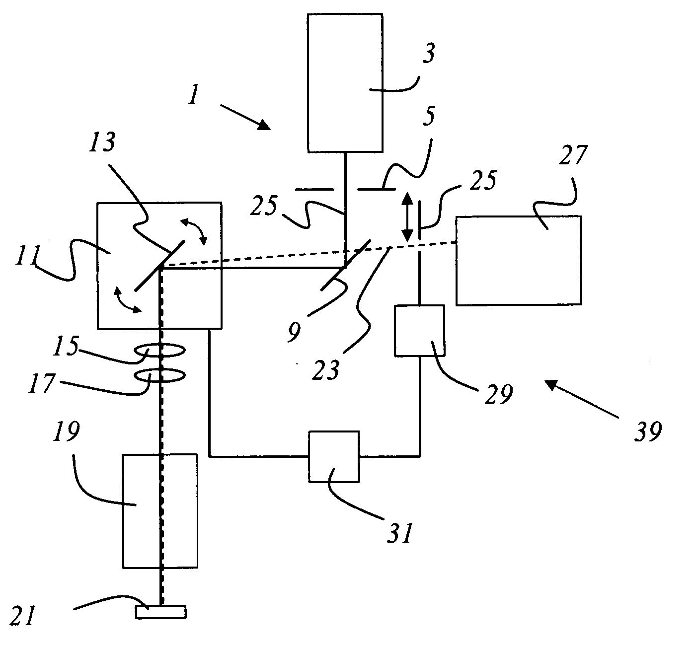
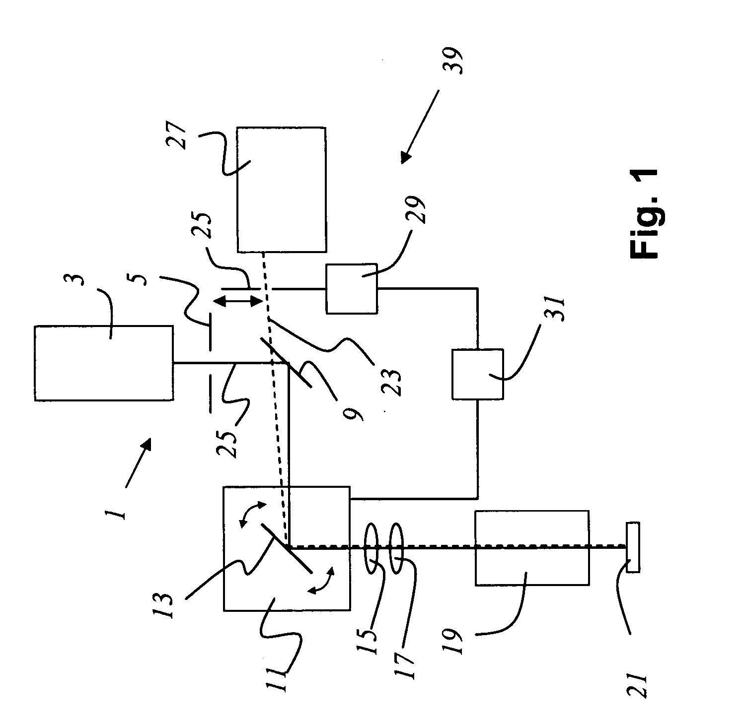
[0023]FIG. 1 shows a confocal scanning microscope according to the present invention, having a point light source 1 that comprises a laser 3 which illuminates an illumination pinhole 5. Light beam 7 passing through illumination pinhole 5 is directed by a main beam splitter 9 to a beam deflection device 11 that contains a gimbal-mounted scanning mirror 13. Beam deflection device 11 guides illuminating light beam 7, through scanning optical system 15, tube optical system 17, and objective 19, over or through sample 21. An illumination beam path is defined by point light source 1, main beam splitter 9, beam deflection device 11, and the aforesaid downstream optical systems. Detected light 23 proceeding from the sample travels through objective 19, tube optical system 17, and scanning optical system 15 and via beam deflection device 11 back to main beam splitter 9, passes through the latter, and then strikes detection pinhole 25. Detected light passing through detection pinhole 25 is de...


PUM


Abstract

A confocal scanning microscope for scanning a sample has an illumination beam path that encompasses at least one point light source and a beam deflection device, and has further a detection beam path that encompasses at least one detection pinhole and the beam deflection device. The routing of the illumination beam path and/or of the detection beam path is adaptable to the scanning speed.

Description

CROSS REFERENCE TO RELATED APPLICATIONS [0001] This application claims priority to German patent application 103 33 445, the subject matter of which is hereby incorporated by reference herein. FIELD OF THE INVENTION [0002] The invention concerns a confocal scanning microscope for scanning a sample. BACKGROUND OF THE INVENTION [0003] In scanning microscopy, a sample is illuminated with a light beam in order to observe the reflected or fluorescent light emitted from the sample. The focus of an illuminating light beam is moved in a specimen plane by means of a controllable beam deflection device, generally by tilting two mirrors, the deflection axes usually being perpendicular to one another so that one mirror deflects in the X direction and the other in the Y direction. Tilting of the mirrors is brought about, for example, by means of galvanometer positioning elements. The power level of the light coming from the specimen is measured as a function of the position of the scanning beam....

Claims


Application Information

Patent Timeline
IPC IPC(8): G02B21/00
CPCG02B21/0052G02B21/0032
Inventor RIEDMANN, JUERGEN
Owner LEICA MICROSYSTEMS CMS GMBH
Why Eureka
Try Eureka