Network address assignment in a passive optical network

a passive optical network and network address technology, applied in the field of computer networking, can solve the problems of wasting ip addresses, consuming an entire subnet scope of ip addresses, and wasting ip addresses, so as to achieve the effect of less class c ip address spaces

Inactive Publication Date: 2005-01-27
CALIX
View PDF28 Cites 10 Cited by
  • Summary
  • Abstract
  • Description
  • Claims
  • Application Information

AI Technical Summary

Benefits of technology

[0004] In general, the invention is directed to techniques for assignment of IP addresses to network nodes in a PON. The invention enables assignment of IP addresses within a common subnet scope to network nodes coupled to different optical fiber links and different interface modules in the PON. In th

Problems solved by technology

Consequently, the group of network nodes served by a PON interface module consumes an entire subnet scope of IP addresses.
Unfortunately, the number of network nodes served by a given PON interface module may be much less than the number of available addresses within the subnet scope, e.g., 255 addresses.
De

Method used


Image

  • Network address assignment in a passive optical network
  • Network address assignment in a passive optical network
  • Network address assignment in a passive optical network

Examples


Embodiment Construction

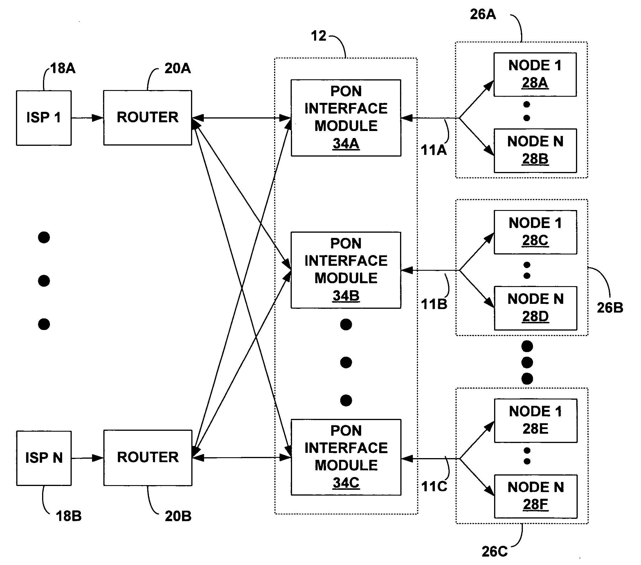
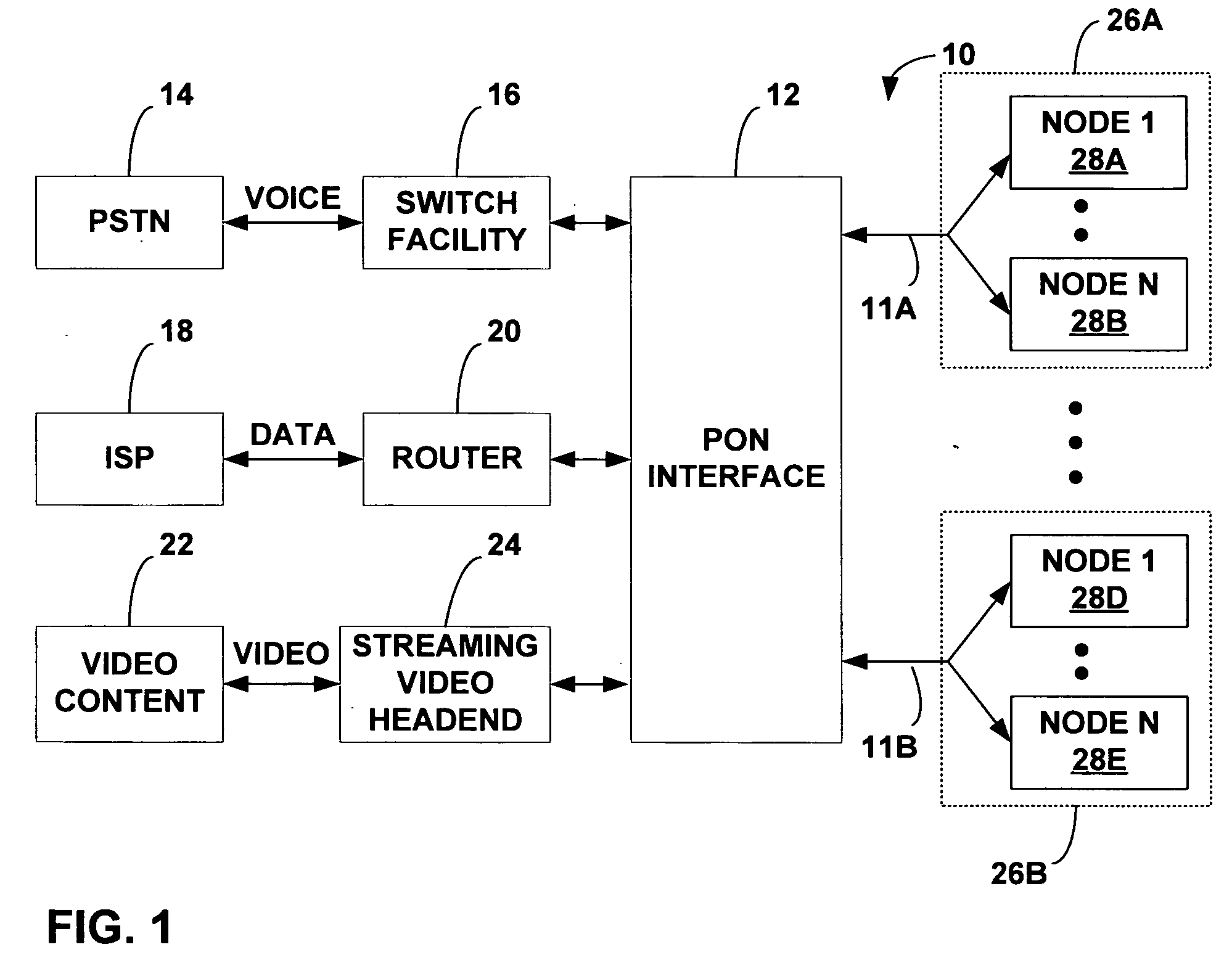
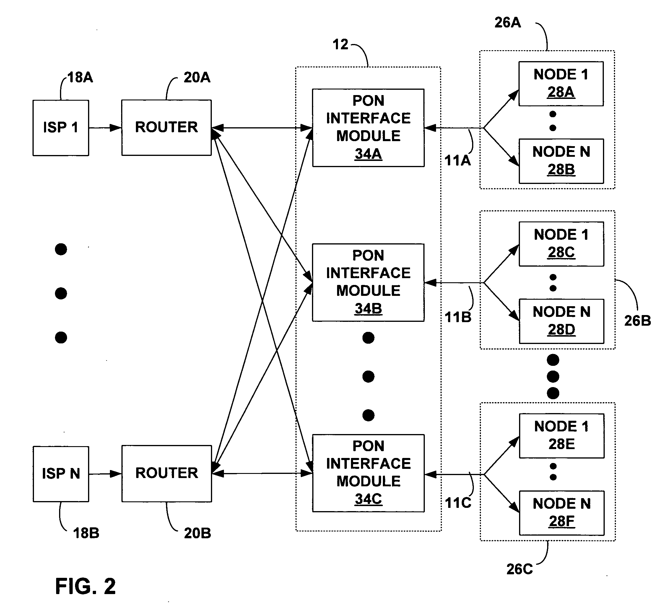
[0018]FIG. 1 is a block diagram illustrating a passive optical network (PON) 10. As will be described, various components of PON 10 may incorporate features that enable IP addresses within a common subnet scope to be assigned to network nodes coupled to different optical fiber links and different interface modules. As shown in FIG. 1, PON 10 can be arranged to deliver voice, data and video content (generally “information”) to a number of network nodes via optical fiber links 11. Exemplary components for implementing a PON are commercially available from Optical Solutions, Inc., of Minneapolis, Minn., and designated by the tradename Fiberpath 400™, including the Fiberdrive™ headend bay interface and the Fiberpoint™ subscriber premise nodes.

[0019] A PON interface 12 may receive voice information, for example, from the public switched telephone network (PSTN) 14 via a switch facility 16. In addition, PON interface 12 may be coupled to one or more Internet service providers (ISP's) on ...


PUM


Abstract

Assignment of network addresses, e.g., IP addresses, to network nodes in a passive optical network (PON) may involve assignment of IP addresses within a common subnet scope to network nodes coupled to different optical fiber links and different interface modules in the PON. In this manner, excessive waste of IP addresses can be avoided. Instead of assigning an entire subnet scope of addresses to the nodes coupled to a single optical fiber link, a common subnet can be allocated across a PON having multiple, independent interfaces, increasing the number of subnet IP addresses that are actually used. Accordingly, the IP address space within a subnet scope can be distributed more efficiently. In addition to conserving IP addresses, the number of subnets allocated by ISPs can be reduced, along with the significant expense incurred by ISPs in reserving and maintaining multiple class C subnets.

Description

TECHNICAL FIELD [0001] The invention relates to computer networking and, more particularly, assignment of network addresses such as IP addresses within a passive optical network (PON). BACKGROUND [0002] A passive optical network (PON) can deliver voice, video and other data among multiple network nodes using a common optical fiber link. Passive optical splitters and combiners enable a number of network nodes to share the optical fiber link. Each network node terminates the optical fiber link for a residential or business subscriber, and is sometimes referred to as a subscriber premises node. A PON typically includes a PON interface having multiple, independent PON interface modules that serve multiple optical fiber links. In the case of data services, the PON interface receives data packets from an Internet service provider for transmission to network nodes. A PON interface module provides an Ethernet interface for transmission and reception of over a particular optical fiber link t...

Claims


Application Information

Patent Timeline
IPC IPC(8): H04J3/16H04L29/12
CPCH04L29/12283H04L29/1282H04L61/6013H04L61/2061H04L61/2015H04L61/5061H04L61/59H04L61/5014
Inventor KOCH, CHRISTOPHER D.JOHNSON, MILTON J.
Owner CALIX
Why Eureka
Try Eureka