Variable displacement pump

a variable-discharge pump and pump technology, applied in the direction of machines/engines, positive-displacement liquid engines, liquid fuel engines, etc., can solve the problems of noise generation, oscillation of cam rings, and possible unstable flow rate of pressurized fluid discharged from the pump, so as to prevent noise occurrence and stabilize the flow rate of pressurized fluid discharge

Active Publication Date: 2005-01-27
HITACHI ASTEMO LTD
View PDF9 Cites 19 Cited by
  • Summary
  • Abstract
  • Description
  • Claims
  • Application Information

AI Technical Summary

Benefits of technology

[0012] It is, therefore, an object of the present invention to provide a variable displacement pump which allows stable flow rate of pressurized fluid discharged from the pump with occurrence of noises restrained.

Problems solved by technology

Thus, the pressure within the first fluid-pressure chamber is abruptly changed from the low pressure to the high pressure, causing oscillation of the cam ring in the swing direction, leading to possible unstableness of the flow rate of pressurized fluid discharged from the pump up to sufficient buildup of the pressure within the first fluid-pressure chamber.
Moreover, oscillation of the cam ring can produce noises.

Method used


Image

  • Variable displacement pump
  • Variable displacement pump
  • Variable displacement pump

Examples


Embodiment Construction

[0021] Referring to the drawings, a description is made about a preferred embodiment of a variable displacement pump according to the present invention.

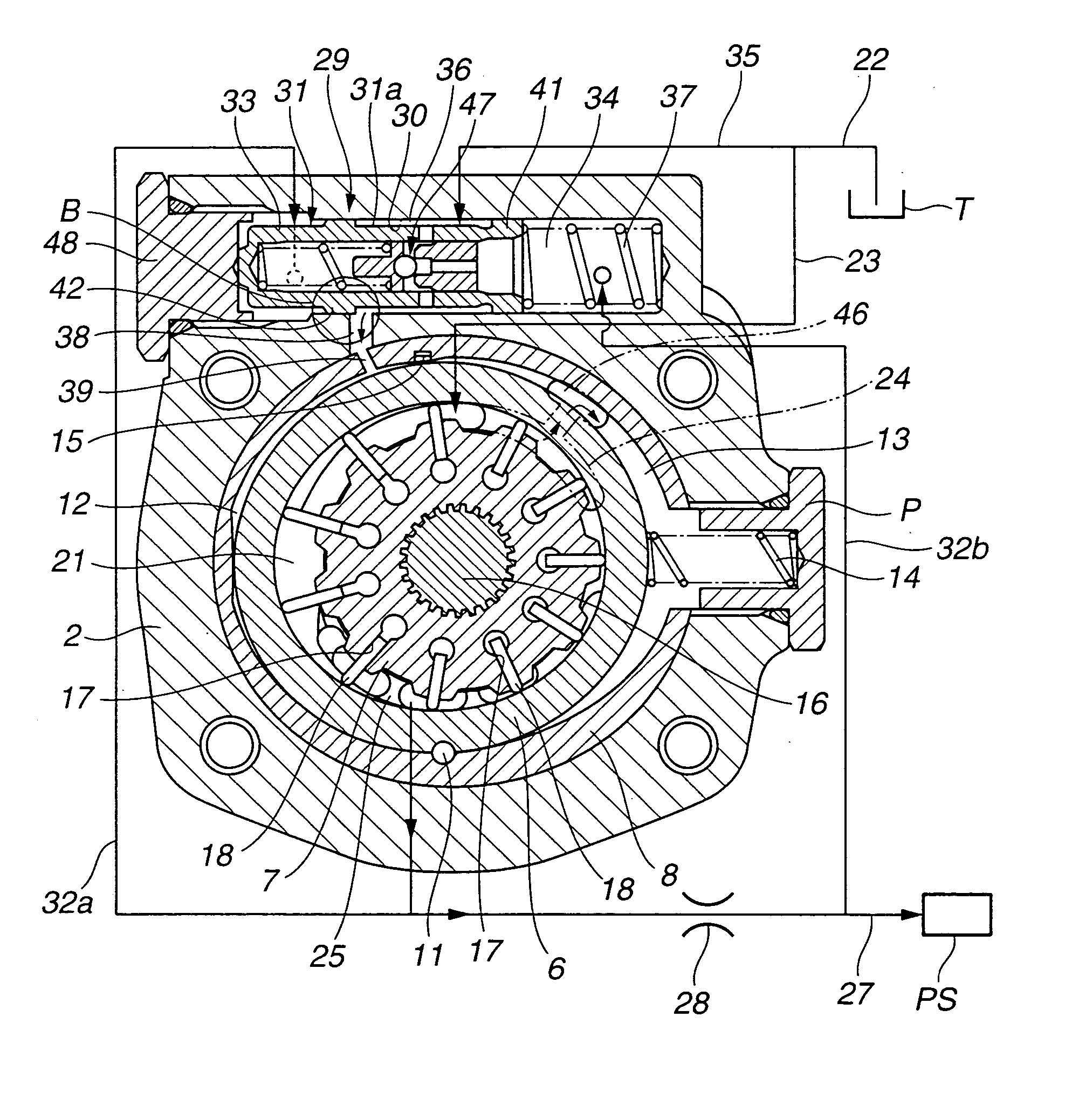
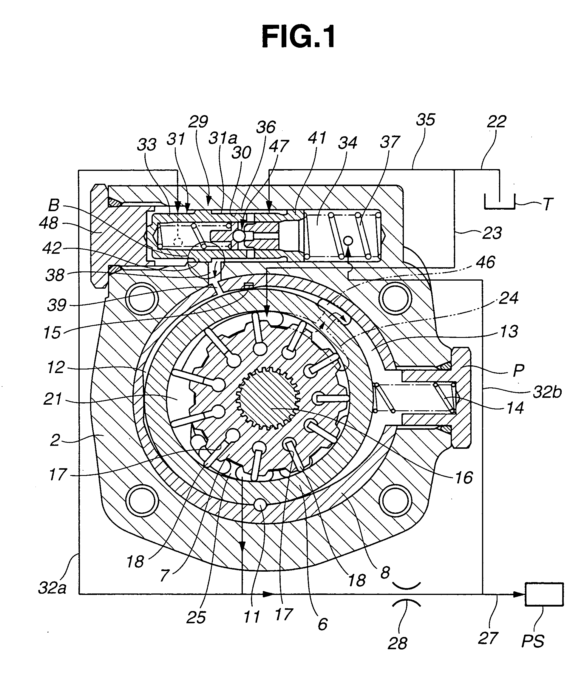
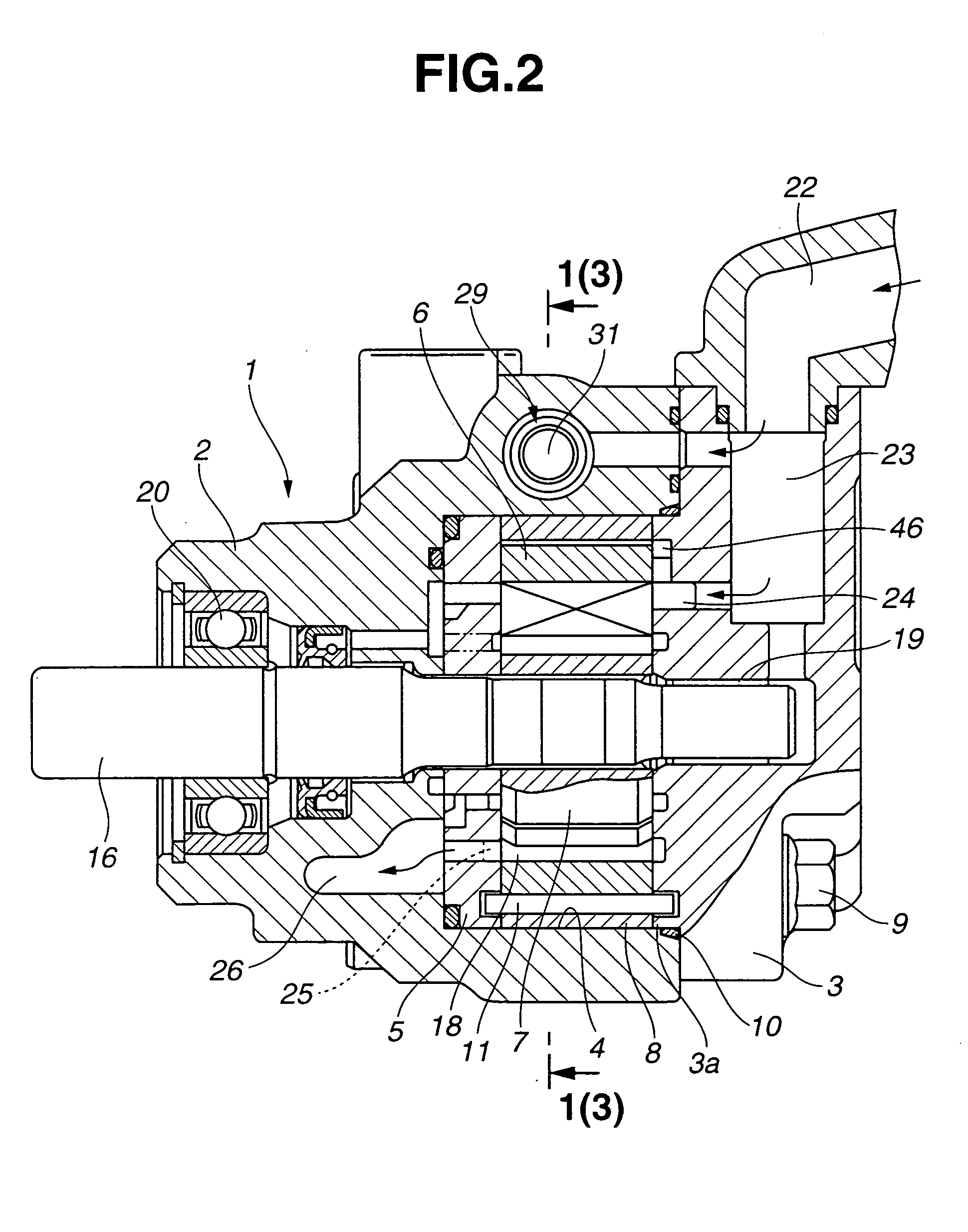
[0022] Referring to FIG. 2, the variable displacement pump serves as a source for supplying the hydraulic pressure to a hydraulic device such as a power steering apparatus, and comprises a pump body 1 including a cup-shaped front body 2 located at the left as viewed in FIG. 2 and a rear body 3 located at the right as viewed in FIG. 2.

[0023] Front body 2 is formed with a concave 4 at an end on the side of rear body 3, in which pump component members such as a pressure plate 5, a cam ring 5, a vane rotor 7, and an adaptor ring 8 are accommodated. With an annular protrusion 3a of rear body 3 engaged in an open end of concave 4, front body 2 is coupled to rear body 3 by a bolt 9. An annular seal member 10 is interposed between the open end of concave 4 and annular protrusion 3a to seal the inside of concave 4.

[0024] Pressure plate 5 i...


PUM


Abstract

A variable displacement pump includes a control valve formed with a high-pressure chamber for introducing therein high-pressure fluid on the upstream side of a metering orifice, a pressure chamber for introducing therein pressure fluid on the downstream side of the metering orifice, a low-pressure chamber arranged between the high-pressure and pressure chambers for introducing therein low-pressure fluid, and a communication passage for providing fluid communication between one of the high-pressure and low-pressure chambers and a first fluid-pressure chamber of the pump. First and second recessed grooves are formed in the outer-peripheral surface of a spool of the control valve to provide fluid communication between the low-pressure and high-pressure chambers through the communication passage of the control valve when the spool carries out selective switching between the high-pressure and low-pressure chambers to supply fluid to the communication passage, thus restraining abrupt pressure rise in the first fluid-pressure chamber.

Description

BACKGROUND OF THE INVENTION [0001] The present invention relates to a variable displacement pump which serves as a source for supplying the hydraulic pressure to a hydraulic device such as an automotive power steering apparatus. [0002] Typically, the variable displacement pump comprises a housing, a cam ring arranged swingably in the housing, first and second fluid-pressure chambers arranged in one and another swing directions of the cam ring, respectively, and a spring arranged in the second fluid-pressure chamber and for biasing the cam ring to the first fluid-pressure chamber. [0003] Arranged rotatably in the cam ring is a vane rotor having an axis offset with respect to the center of the cam ring. The vane rotor comprises slots formed radially in the outer periphery and vanes held therein to be movable with respect to the inner-peripheral surface of the cam ring. [0004] A metering orifice is provided to a discharge passage for supplying to a hydraulic device pressurized fluid di...

Claims


Application Information

Patent Timeline
Patent Type & Authority Applications(United States)
IPC IPC(8): F04C2/344F04C14/08F04C14/22F04C15/06
CPCF04C2/3441F04C2270/20F04C14/226F04C14/08F04C2/344
Inventor UCHINO, KAZUYOSHIMIYAZAWA, SHIGEYUKI
Owner HITACHI ASTEMO LTD
Why Eureka
Try Eureka