Controlled release of additives in fluid systems
a technology of fluid system and additives, applied in flow mixers, chemical/physical processes, machines/engines, etc., can solve the problems of depletion and/or insufficient of additives initially present in fluid, and the above-described devices suffer from a variety of limitations
- Summary
- Abstract
- Description
- Claims
- Application Information
AI Technical Summary
Benefits of technology
Problems solved by technology
Method used
Image
Examples
example 1
Dual Release Vessel
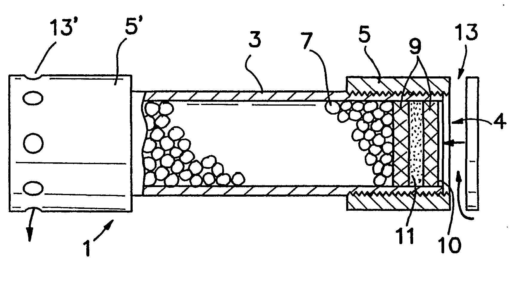
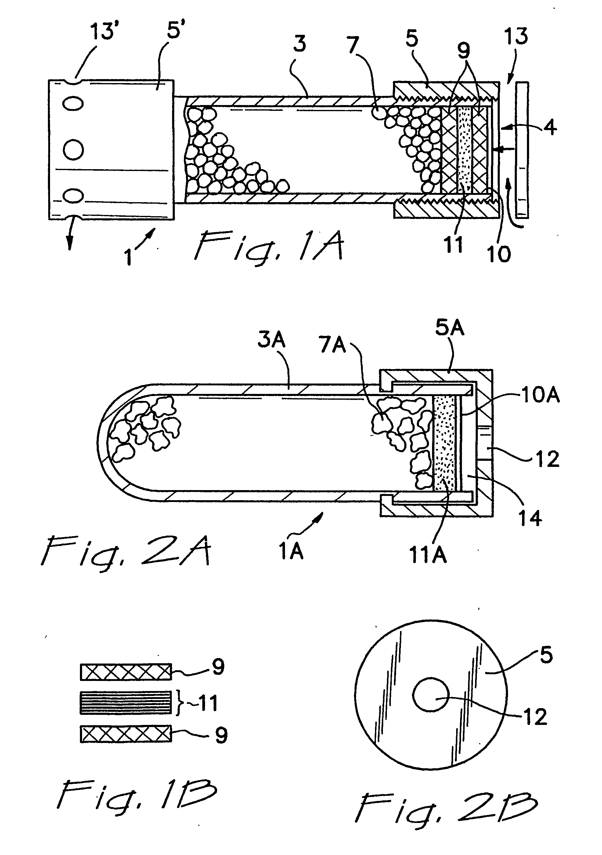
Referring now to FIG. 1A, container 1 comprises a solid, open ended, cylindrically shaped PVC casing 3 and end caps 5 and 5′, which are screwed onto the casing. The casing 3 has two open ends 4. Provided within the casing are particles 7 of a fluid material additive composition, which is retained within the casing by inner and outer screens 9 and fluid material-permeable membrane 11. Wax seal 10 is applied to outer screen 9 for shipment / storage of the container. Alternatively, or in addition, the wax seal can be applied to inner screen 9. If the seal is located on the top, the seal will come in contact with the fluid material substantially immediately and effect a faster release of the fluid material additive composition. If the seal is located on the bottom, the fluid material must first pass through the membrane in order to dissolve the wax. Such placement of the seal can be useful to delay the initial release of fluid material additive composition, if such de...
example 2
Single Release Vessel
FIG. 2A depicts a cross-sectional view of an alternative embodiment of the present container, shown as 1A. In this embodiment, casing 3A is structured similarly to casing 3, but has only a single open end 14, which is capped with end cap 5A. The end cap 5A is press-fit onto casing 3A, rather than being screwed on, and is further provided with release orifice 12 that at least assists in controlling release of additive from the container 1. In this embodiment, membrane 11A is sufficiently rigid to hold it in place and retain particles 7A. Wax seal 10A is located in proximity to, preferably on, membrane 11A to seal container 1A for shipment / storage. FIG. 2B shows an end view of the end cap 5A shown in FIG. 2A, clearly showing orifice 12. Container 1A is effective, when placed in contact with fluid material, to release additive composition from casing 3A into the fluid material in a sustained manner over a period of time.
example 3
Dual Release Configuration
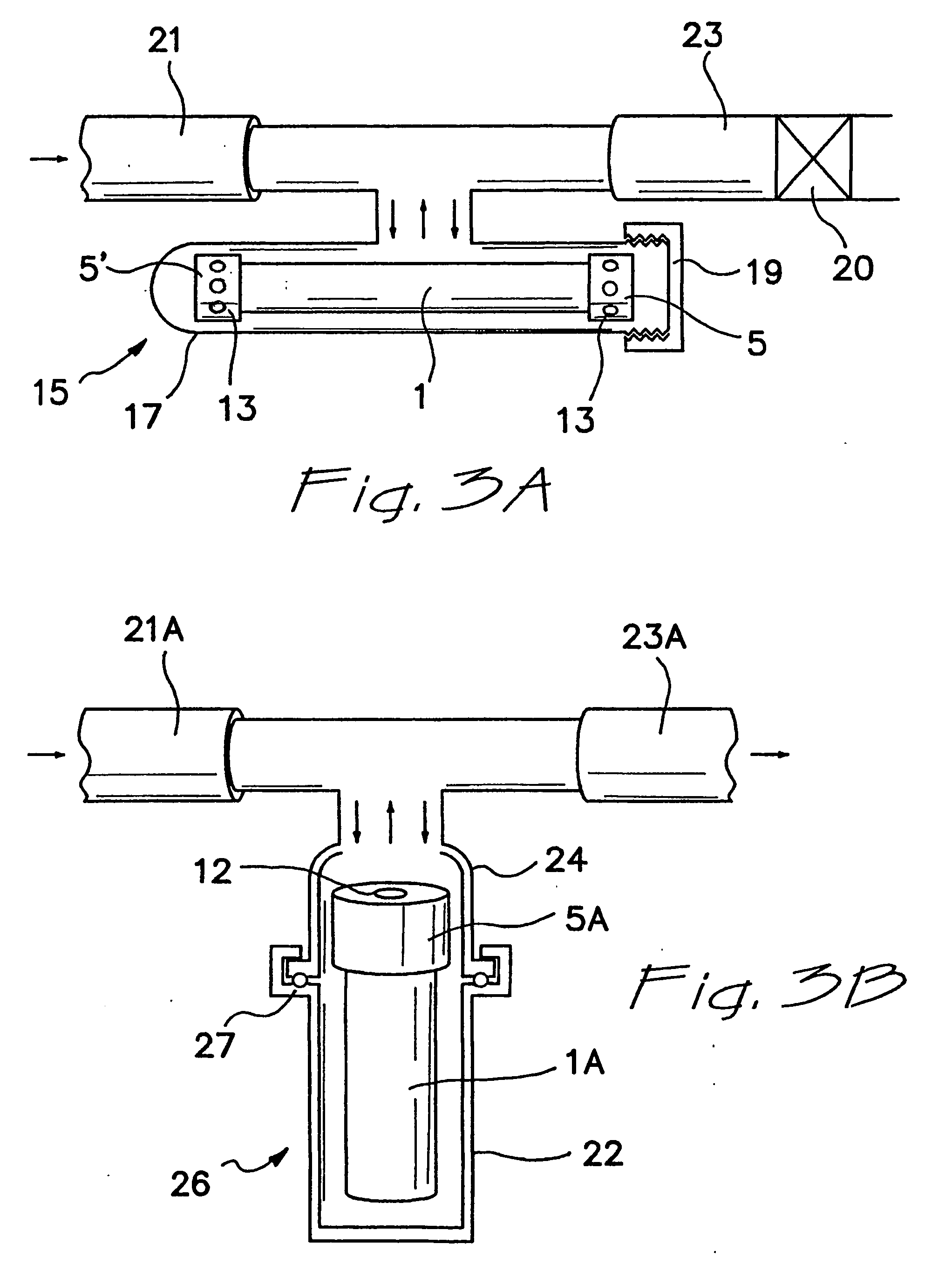
FIG. 3A illustrates one aspect of the present invention in which a dual-release container 1A (as shown in FIG. 1A) is employed in a “bypass” additive release vessel. In particular, container 1A lies horizontally in housing 15 and is held therein by screw cap 19, which is secured to housing body 17. Fluid material flow from inlet line 21 enters housing 15 and exits via exit line 23. While inside the housing 15, fluid material circulates through openings 13 and 13′ in end caps 5 and 5′, respectively, causing the release of additive from container 1A into the fluid material. Generally, fluid material flows into the housing 15 by the action of a fluid material pump (not shown) of the fluid material system, it being understood that gravity may also play a role. In addition, a fluid material filter element 20, for example, of conventional and well known design, is located in exit or outlet line 23. It is understood that filter element 20 could alternatively be l...
PUM
| Property | Measurement | Unit |
|---|---|---|
| pore size | aaaaa | aaaaa |
| pore size | aaaaa | aaaaa |
| pore size | aaaaa | aaaaa |
Abstract
Description
Claims
Application Information
 - R&D
- Intellectual Property
- Life Sciences
- Materials
- Tech Scout
- Unparalleled Data Quality
- Higher Quality Content
- 60% Fewer Hallucinations
Browse by: Latest US Patents, China's latest patents, Technical Efficacy Thesaurus, Application Domain, Technology Topic, Popular Technical Reports.
© 2025 PatSnap. All rights reserved.Legal|Privacy policy|Modern Slavery Act Transparency Statement|Sitemap|About US| Contact US: help@patsnap.com


