Apparatus and Methods for Controlled Release of Additive Compositions
a technology of additive compositions and apparatuses, applied in chemical apparatus and processes, separation processes, filtration separation, etc., can solve the problems of large additive quantities, damage and failure of pump seals, and plagued liquids in various systems, so as to achieve the effect of providing and controlling the effective release of additive compositions into liquid compositions, and being convenient and effectiv
- Summary
- Abstract
- Description
- Claims
- Application Information
AI Technical Summary
Benefits of technology
Problems solved by technology
Method used
Image
Examples
example 1
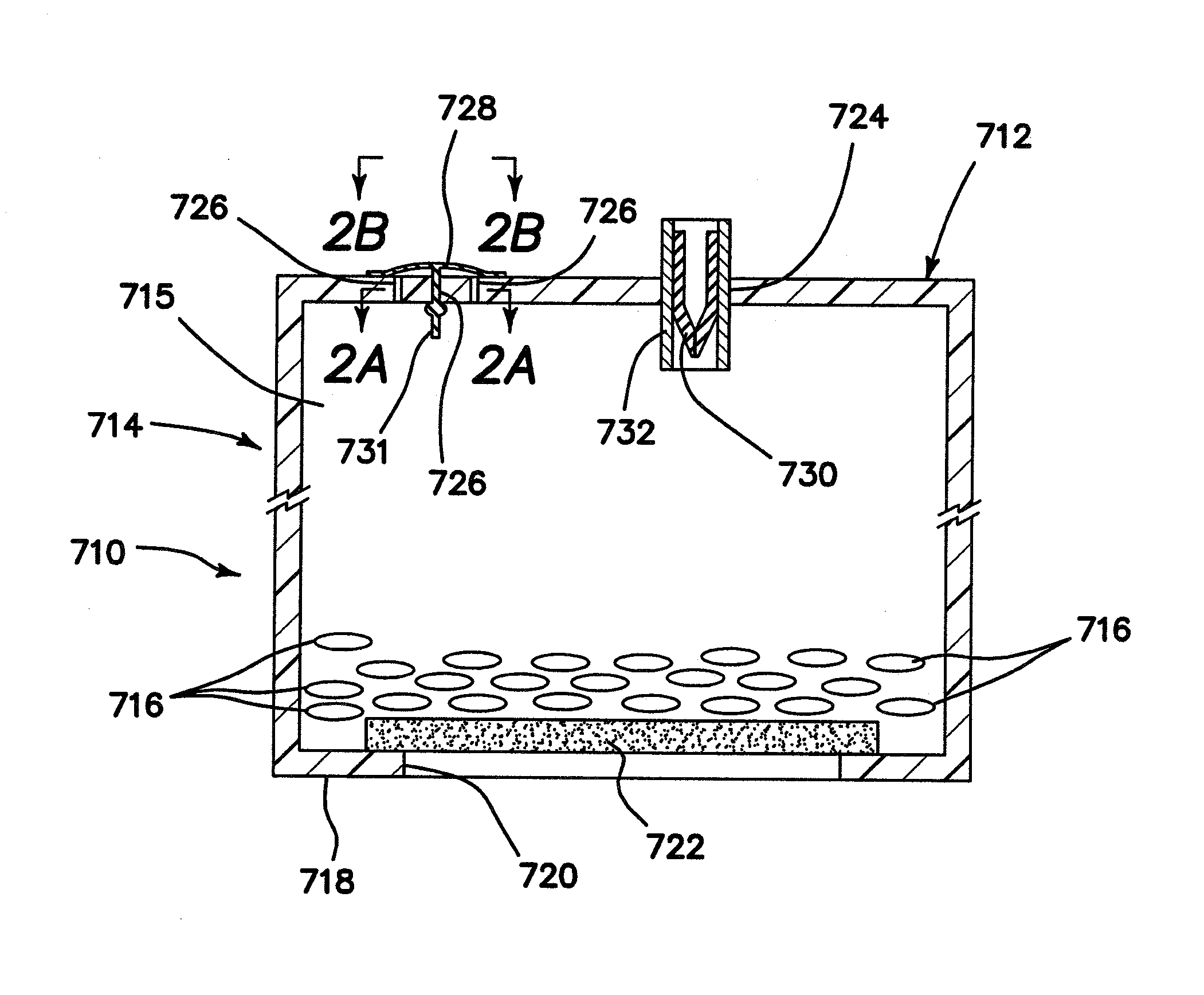
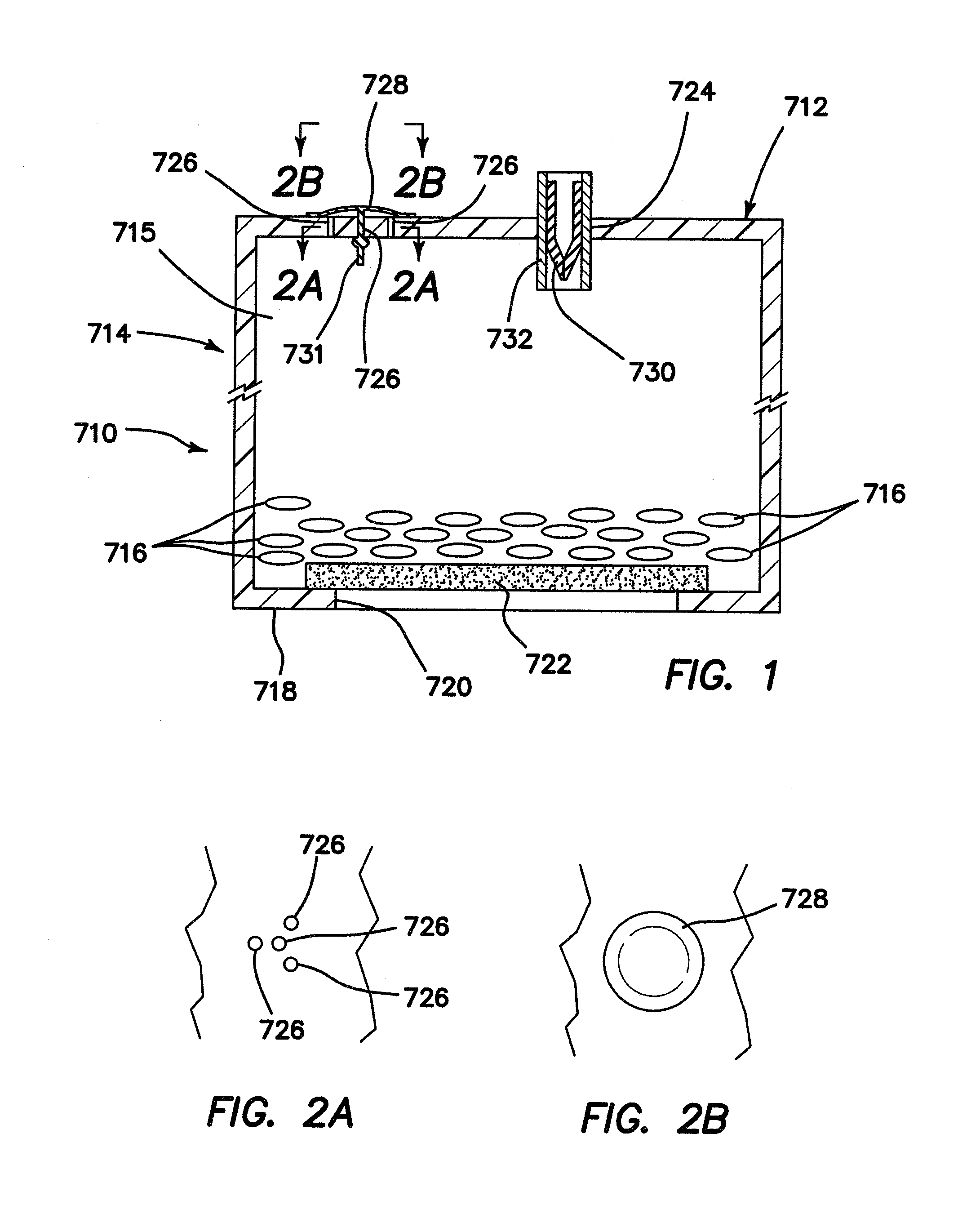
[0101]FIGS. 1, 2A and 2B show component parts of an additive composition container 710 in accordance with the present invention. Container 710 includes a casing or casing body 714. The casing body 714 includes or defines an interior hollow space or hollow interior 715 in which particles 716 of an additive composition are placed.
[0102]The casing body 714 may comprise or be made of any suitable material, for example, one or more polymeric materials. Examples of useful polymeric materials include, without limitation, polyolefins, polyamides (nylon), any suitable polymeric material, such as those which are conventional and / or well known and / or commercially available. Such polymeric materials may include polyolefins, such as polypropylene, polyethylene and the like.
[0103]The casing body 714 may also be molded using conventional and well known techniques. The casing body may be made using any suitable manufacturing process, for example, any conventional and / or well known process for makin...
example 2
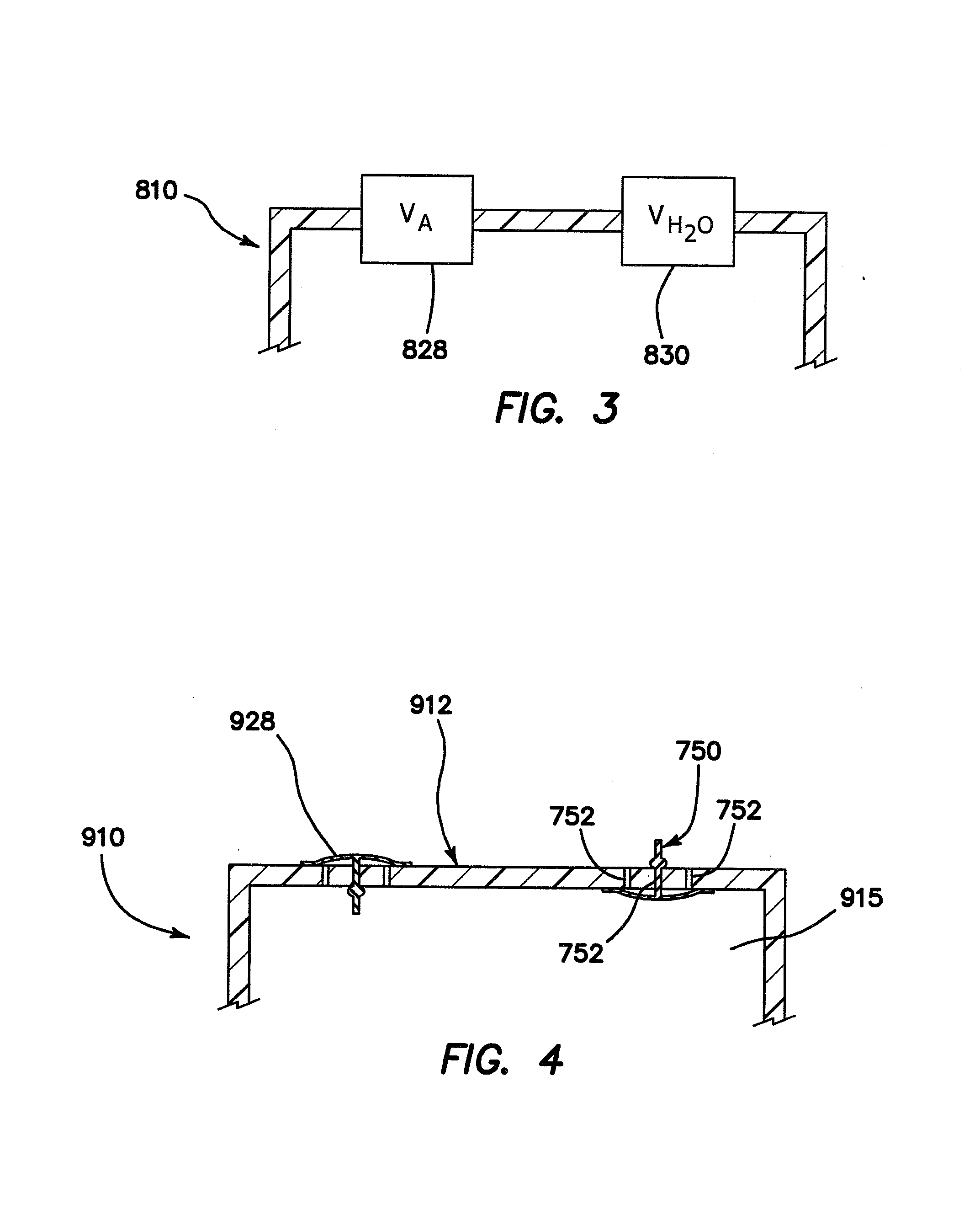
[0125]FIG. 3 is a partial view of a container 810 which, except as expressly set forth herein, is substantially similar to container 710. Elements of container 810 which correspond to elements of container 710 are identified with the same reference numeral as shown in FIGS. 1, 2A and 2B increased by 100.
[0126]FIG. 3 illustrate that container 810 is equipped with an air valve 828 of any suitable construction, and with a liquid valve 830 of any suitable construction.
[0127]Air valve 828 may be structured and configured to allow air and / or vapor to be released from the hollow interior 815, and may further operate to substantially prevent liquid from passing across the valve 828 either into or out of the hollow interior 815. Air valve 828 may be selected independently from liquid valve 830. Examples of valves which may be employed as umbrella valves, duckbill valves, ball valves and the like and combinations thereof.
[0128]Liquid valve 830 may be structured and configured to prevent or su...
example 3
[0129]FIG. 4 is a partial view of a container 910 which, except as expressly set forth herein, is substantially similar to container 710. Elements of container 910 which correspond to elements of container 710 are identified with the same reference numeral as shown in FIGS. 1, 2A and 2B increased by 200.
[0130]The primary difference between container 910 and container 710 is that the duckbill valve (water valve 730 in FIG. 1) has been replaced by umbrella valve 750. In order to accommodate umbrella valve 750, a plurality, e.g., four, holes 752 are provided in the upper wall 912 of container 710. These holes may be as in FIG. 2A. Umbrella valve 750 is structured and configured to allow liquid to flow into the hollow interior across the liquid valve 750 and to prevent liquid from passing from the hollow interior 915 of container 910 across umbrella valve 750. Thus, as shown in FIG. 4, both the air valve 928 and the liquid valve 750 are umbrella valves, each of which is configured or po...
PUM
| Property | Measurement | Unit |
|---|---|---|
| Time | aaaaa | aaaaa |
| Volume | aaaaa | aaaaa |
| Volume | aaaaa | aaaaa |
Abstract
Description
Claims
Application Information
 - R&D
- Intellectual Property
- Life Sciences
- Materials
- Tech Scout
- Unparalleled Data Quality
- Higher Quality Content
- 60% Fewer Hallucinations
Browse by: Latest US Patents, China's latest patents, Technical Efficacy Thesaurus, Application Domain, Technology Topic, Popular Technical Reports.
© 2025 PatSnap. All rights reserved.Legal|Privacy policy|Modern Slavery Act Transparency Statement|Sitemap|About US| Contact US: help@patsnap.com


