System and method for coding information on a biosensor test strip

a biosensor and information technology, applied in the field of system and method for coding information on biosensor test strips, can solve the problems of deprived diabetics of use of fingers, hands, feet, and prior art attempts to code information onto test strips for reading by test meters, and severely limit the amount of information that can be coded

Active Publication Date: 2005-01-27
ROCHE DIABETES CARE INC +1
View PDF13 Cites 166 Cited by
  • Summary
  • Abstract
  • Description
  • Claims
  • Application Information

AI Technical Summary

Benefits of technology

[0011] In one form of the invention, a method for forming a test strip for measuring a concentration of an analyte of interest in a biological fluid is disclosed, the method comprising the steps of: providing a basic test strip design comprising: a substrate having a surface and at least one measurement electrode formed thereon; a plurality of conductive contact pads formed upon the substrate surface, including at least one information contact pad and at least one measurement contact pad; and a plurality of potential conductive links conductively coupling various ones of the plurality of contact pads; wherein the at least one information contact pad is not coupled to any of the at least one measurement electrodes except by one or more of the plurality of potential conductive links, and the at least one measurement contact pad is coupled to one of the at least one measurement electrodes by a path other than one or more of the plurality of potential conductive links; defining a set of valid test strip designs; wherein each one of the set of valid test strip designs incorporates none, one or more than one of the plurality of potential conductive links; and wherein at least one of the plurality of potential conductive links couples a first one of the information contact pads to a first one of the measurement contact pads in a first valid test strip design, and at least one of the plurality of potential conductive links couples the first one of the information contact pads to a second one of the measurement contact pads in a second valid test strip design; selecting one design from the set of valid test strip designs; and forming a test strip per said selected one design.
[0012] In another form of the invention, a plurality of test strips for measuring a concentration of an analyte of interest in a biological fluid is disclosed, each of the plurality of test strips being substantially identical to one another except for a presence or absence of a plurality of potential conductive links, at least one of the test strips comprising: a substrate having a surface and at least one measurement electrode formed thereon; a plurality of conductive contact pads formed upon the substrate surface, including at least one information contact pad and at least one measurement contact pad; and a plurality of conductive links selected from the plurality of potential conductive links, wherein the plurality of conductive links conductively couple at least three contact pads together; wherein the at least one information contact pad is not coupled to any of the at least one measurement electrodes except by one or more of the plurality of potential conductive links, and the at least one measurement contact pad is coupled to one of the at least one measurement electrodes by a path other than one or more of the plurality of potential conductive links.
[0013] In another form of the invention, a method for forming a test strip for measuring a concentration of an analyte of interest in a biological fluid is disclosed, the method comprising the steps of: providing a basic test strip design comprising: a substrate having a surface and at least one measurement electrode formed thereon; a plurality of conductive contact pads formed upon the substrate surface, including at least one information contact pad and at least one measurement contact pad; and a plurality of potential conductive links conductively coupling various ones of the plurality of contact pads; wherein the at least one information contact pad is not coupled to any of the at least one measurement electrodes except by one or more of the plurality of potential conductive links, and the at least one measurement contact pad is coupled to one of the at least one measurement electrodes by a path other than one or more of the plurality of potential conductive links; defining a set of valid test strip designs; wherein each one of the set of valid test strip designs incorporates none, one or more than one of the plurality of potential conductive links; and wherein at least one of the set of valid test strip designs includes conductive links that conductively couple at least three contact pads together; selecting one design from the set of valid test strip designs; and forming a test strip per said selected one design.
[0014] In another form of the invention, a test strip for measuring a concentration of an analyte of interest in a biological fluid is disclosed, the test strip comprising: a substrate having a surface and at least one measurement electrode formed thereon; a plurality of conductive contact pads formed upon the substrate surface, including at least one information contact pad and at least one measurement contact pad; and at least one conductive link conductively coupling at least three of the contact pads; wherein the at least one information contact pad is not coupled to any of the at least one measurement electrodes except by one or more of the at least one conductive links, and the at least one measurement contact pad is coupled to one of the at least one measurement electrodes by a path other than one or more of the at least one conductive links.

Problems solved by technology

Failure to do so can produce extreme complications, including blindness and loss of circulation in the extremities, which can ultimately deprive the diabetic of use of his or her fingers, hands, feet, etc.
Prior art attempts to code information onto the test strip for reading by the test meter have suffered from many problems, including a severely limited amount of information that can be coded and the use of relatively large amounts of test strip surface area for the information coding function.

Method used


Image

  • System and method for coding information on a biosensor test strip
  • System and method for coding information on a biosensor test strip
  • System and method for coding information on a biosensor test strip

Examples


first embodiment

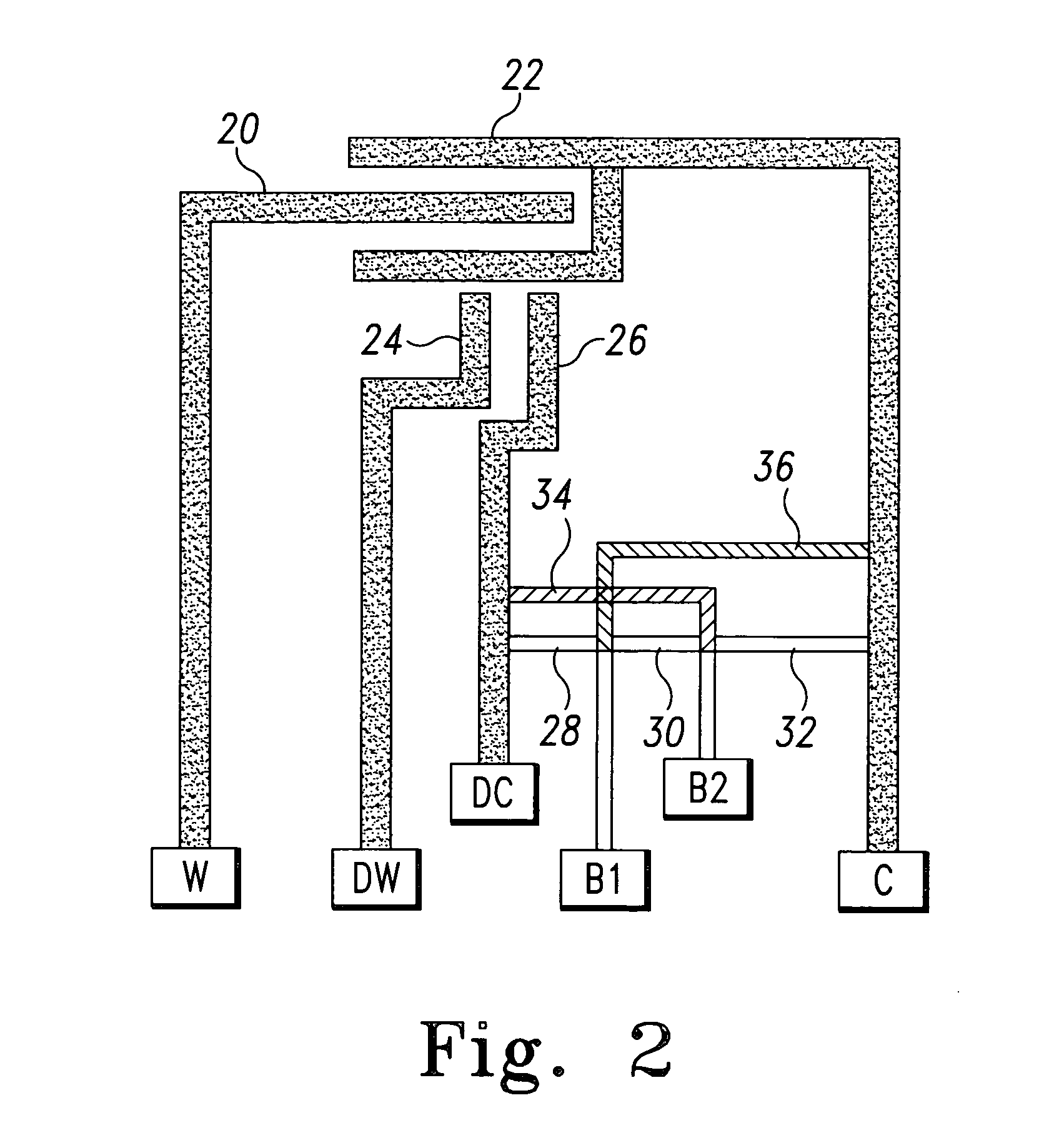
[0048] In the present invention, information about the test strip can be coded directly onto the test strip by the addition of two or more contact pads dedicated to reading such coded information. As illustrated in FIG. 2, a pair of additional information contact pads B1 and B2 are added to the proximal end of the test strip. Additionally, potential conductive links between the information contact pads B1 and B2 and between them and measurement contact pads connected to test strip measurement electrodes are identified at 28, 30, 32, 34 and 36. These links are denominated as potential conductive links because they may either be present or absent in the finished test strip, depending upon the information that is to be coded onto the test strip. Therefore, a “potential conductive link” indicates a conductive link that is found on some, but not all, of a group of otherwise substantially identical test strips. As used herein, the phrase “information contact pad” is defined as a contact p...

second embodiment

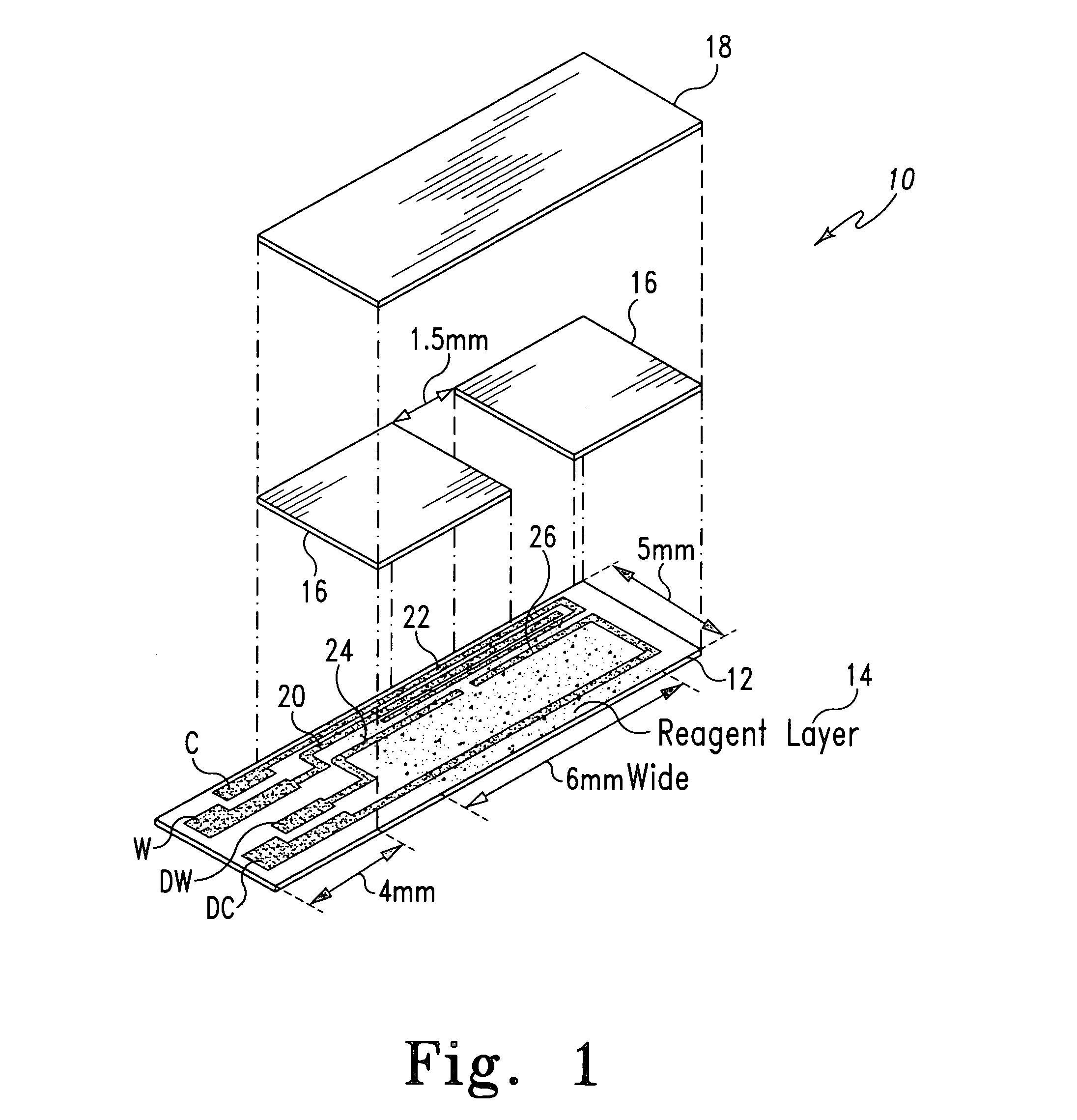
[0084] A second embodiment test strip configuration that allows information to be encoded directly onto the test strip is illustrated in FIG. 10 and indicated generally at 300. The test strip 300 may preferably be formed generally as described above with respect to the test strips 10 and 401, with working 320, counter 322, dose sufficiency working 324, and dose sufficiency counter 326 electrodes may be formed as shown and coupled, respectively, to measurement contact pads W, C, DW and DC. These contact pads provide a conductive area upon the test strip 300 to be contacted by an electrical connector contact of the test meter once the test strip 300 is inserted into the test meter. The test strip may be formed with a sample inlet in the distal end of the test strip (as shown in FIG. 10), or with a sample inlet on the side of the test strip as shown in FIG. 1. The functionality of the information encoding portion thereof is not affected by the positioning of the measurement electrodes ...

third embodiment

[0089] The laser ablation process described hereinabove allows for resolution of test strip conductive features not previously achievable using prior art techniques such as screen printing and photolithography. Because of this, relatively large quantities of data can be coded onto the test strip when the conductive features are formed using the laser ablation process. For example, the present invention is illustrated in FIG. 11 and indicated generally at 500. The test strip 500 is similar to the test strip 300 of FIG. 10, except that the resolution of the laser ablation process allows for an even greater number of contact pads to be formed on the test strip. Equivalent structures in FIG. 11 are given the same reference designators as used in FIG. 10. A total of sixteen contact pads are formed on the test strip 500, with B1-B10 being designated as information contact pads in addition to the measurement contact pads W, WS, C, CS, DW and DC coupled to working 520, counter 522, dose suf...


PUM

PropertyMeasurementUnit
thickaaaaaaaaaa
thickaaaaaaaaaa
widthaaaaaaaaaa

Abstract

The present invention provides a test strip for measuring a concentration of an analyte of interest in a biological fluid, wherein the test strip may be encoded with information that can be read by a test meter into which the test strip is inserted.

Description

REFERENCE TO RELATED APPLICATIONS [0001] This application is also related to applications titled DEVICES & METHODS RELATING TO ANALYTE SENSORS (U.S. Patent Application Ser. No. 60 / 480,397, filed Jun. 20, 2003) and BIOSENSOR AND METHOD OF MAKING (attorney docket number 7404-480 which is being filed of even date herewith), and which are all incorporated herein by reference in their entireties. This application claims the benefit of U.S. Provisional Application No. 60 / 480,199, filed Jun. 20, 2003, the contents of which are hereby incorporated by reference herein.TECHNICAL FIELD OF THE INVENTION [0002] The present invention relates to an apparatus for use in measuring concentrations of an analyte in a biological fluid. The invention relates more particularly to a system and method for coding information on a biosensor test strip. BACKGROUND OF THE INVENTION [0003] Measuring the concentration of substances in biological fluids is an important tool for the diagnosis and treatment of many ...

Claims


Application Information

Patent Timeline
Patent Type & Authority Applications(United States)
IPC IPC(8): C12M1/34C12Q1/68G01N33/558
CPCG01N33/48771G01N33/558
Inventor GROLL, HENNING
Owner ROCHE DIABETES CARE INC
Why Eureka
Try Eureka