Fluid mixing in low aspect ratio chambers

a technology of low aspect ratio and mixing chamber, which is applied in the direction of fluid speed measurement, flow mixer, flat carrier support, etc., can solve the problems of high quality microarray processing, limited sensitivity, and difficult detection of low-expression genes

Inactive Publication Date: 2005-01-27
ADEY NILS +6
View PDF99 Cites 114 Cited by
  • Summary
  • Abstract
  • Description
  • Claims
  • Application Information

AI Technical Summary

Benefits of technology

[0014] Bladders are activated by positive and negative air (or other gas) pressures that may be generated remote to the microfluidic device. Alternatively, water or other liquid may be pumped in and out of the bladders to generate deflec

Problems solved by technology

However, some of the current limitations of microarrays are the time and care required to process slides, the difficulty in obtaining consistent, high quality results, and limited sensitivity, which makes detection of low-expression genes difficult.
The need for high quality microarray processing is particularly pronounced because individual microarray slides are expensive and only limited quantities of the samples used in the reactions may be available, making it particularly important to obtain good results consistently.
However, when small quant

Method used


Image

  • Fluid mixing in low aspect ratio chambers
  • Fluid mixing in low aspect ratio chambers
  • Fluid mixing in low aspect ratio chambers

Examples


example 1

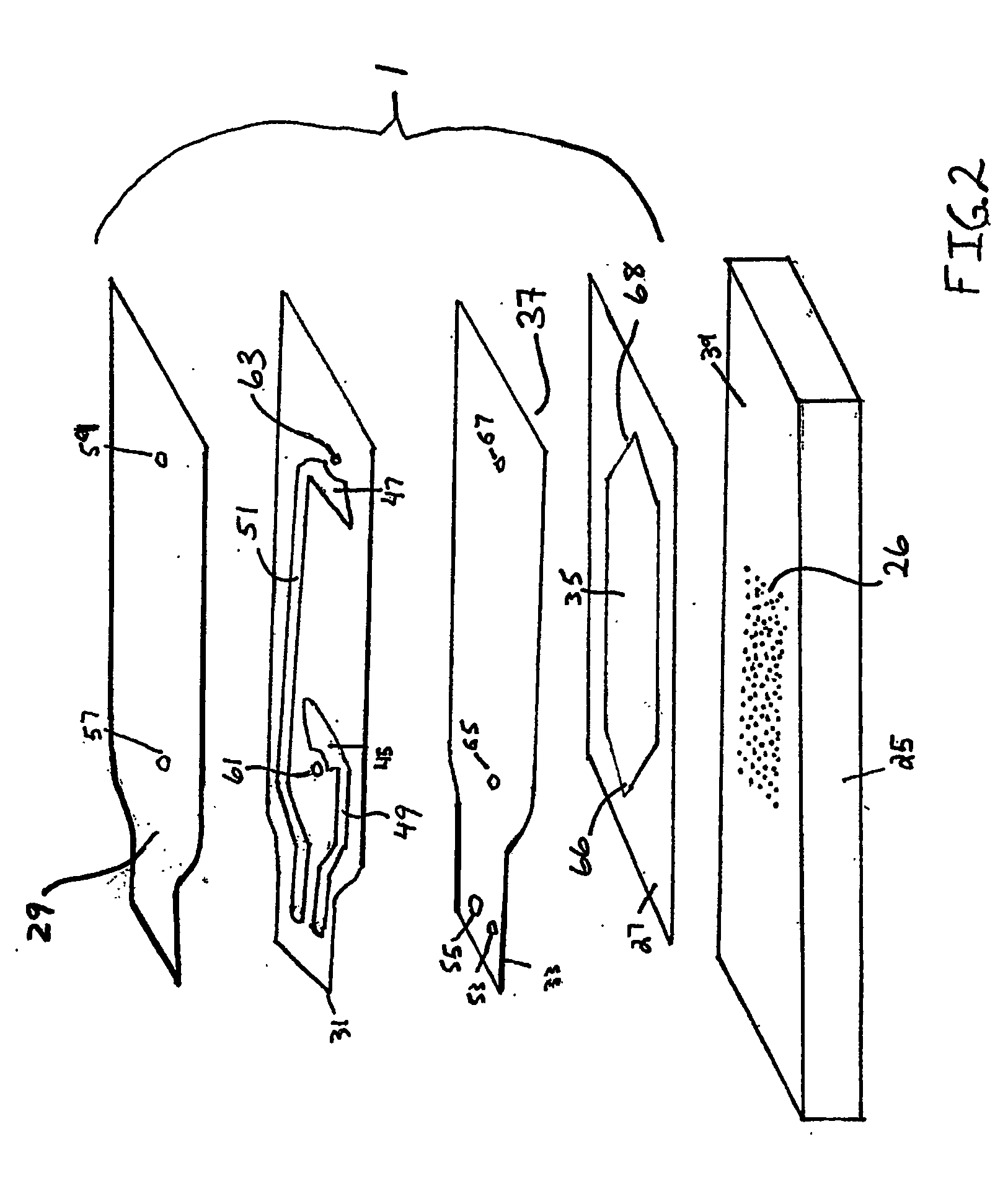
[0033]FIG. 2 depicts a first exemplary embodiment of the invention in the form of an adhesive laminate microarray interface device designed for performing hybridizations on a conventional 1″×3″ microarray slide. The device illustrated in FIG. 2 is described more fully in commonly owned patent application PCT / US02 / ______ (Attorney Docket No. 3153.2.17). The microarray interface device 1 is designed to attach to a glass microarray slide 25 by means of an adhesive gasket 27 to form a hybridization chamber, equivalent to corresponding chamber 3 in FIG. 1, which contains a microarray of arrayed spots 26 of DNA or other material of interest. The device is useful for microarray processing, because providing mixing of labeled target solution during the hybridization process in a low volume hybridization chamber may lead to improved sensitivity and more reproducible microarray processing. The microarray interface device is particularly designed for use with conventional microarray slides, bu...

example 2

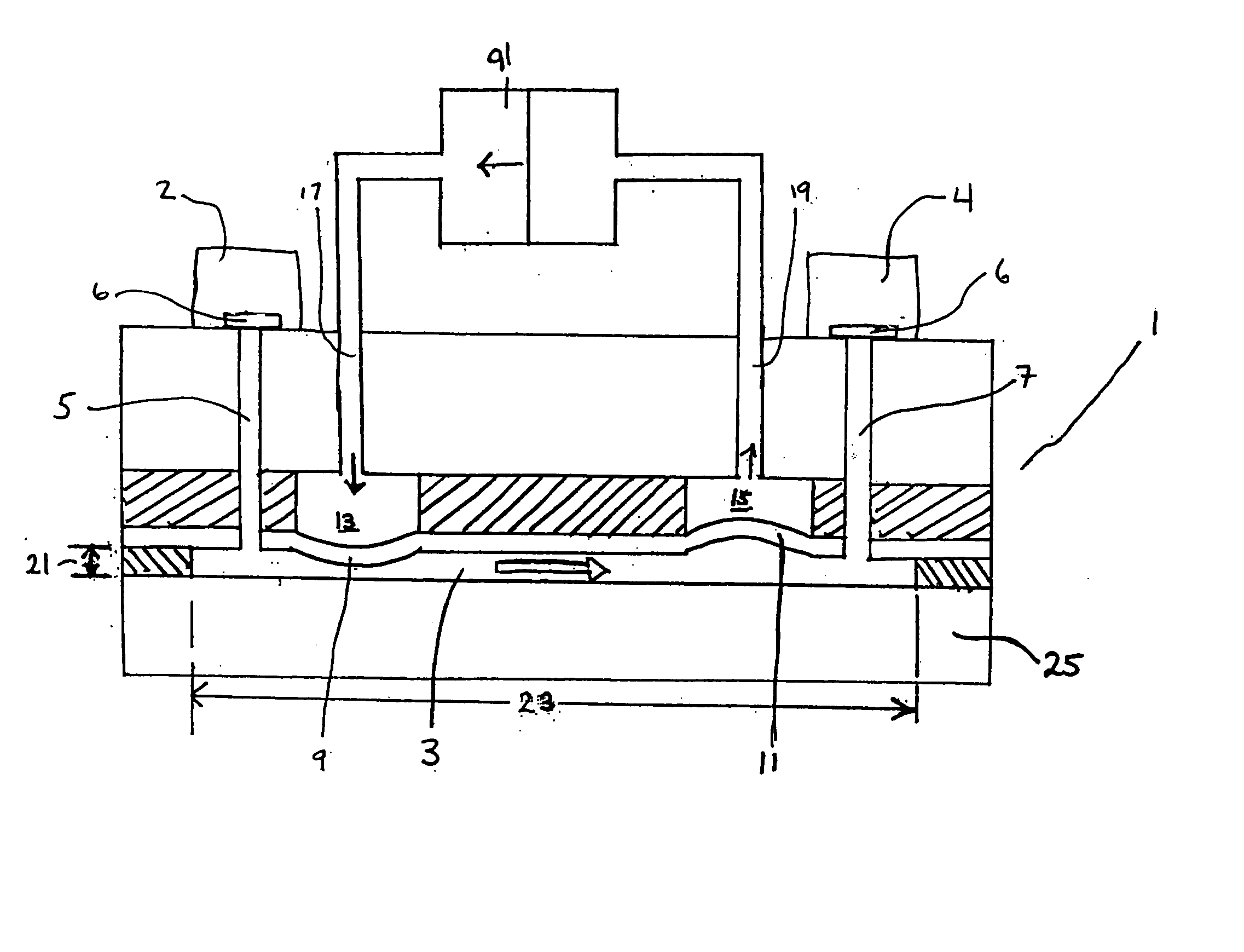
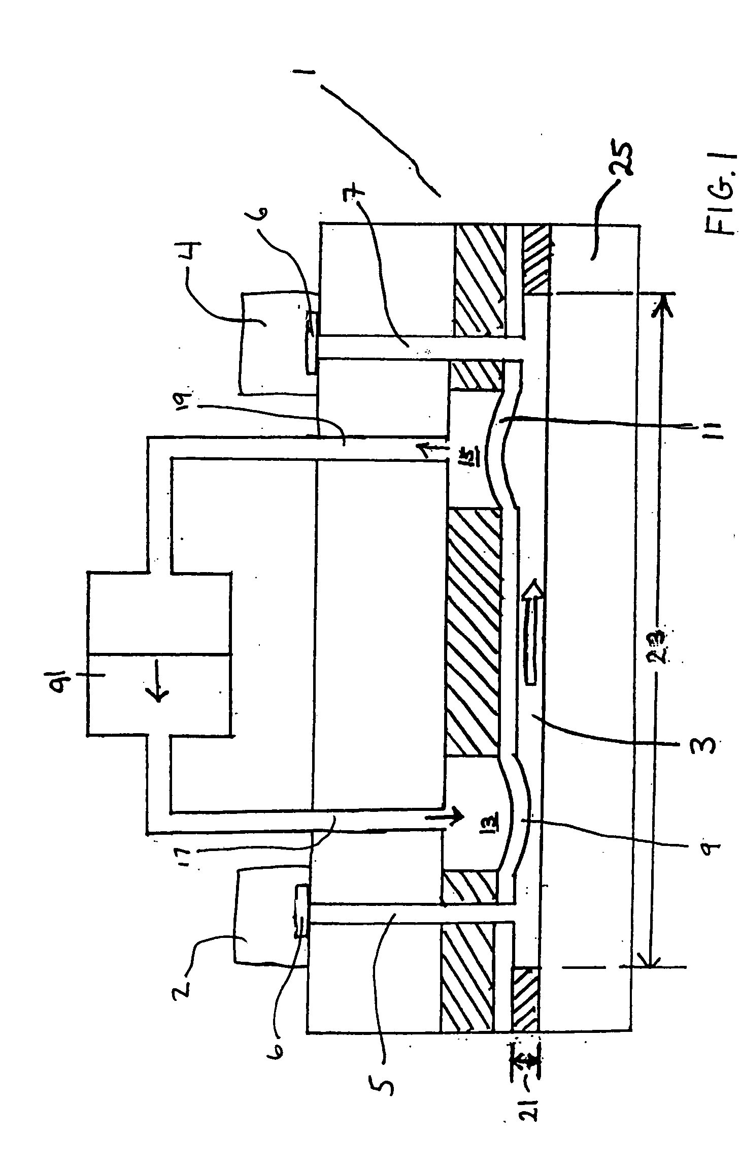
[0037]FIG. 3 depicts an alternative embodiment of the invention in which mixing bladders for generating pneumatic mixing are incorporated into a “hard shell” microarray interface device. This device is functionally similar to the device of FIG. 2, in that it includes a low aspect ratio reaction or hybridization chamber, like reaction chamber 3 in FIG. 1, having a length and width defined by a perimeter wall 70 formed by an opening 69 in a gasket 71. The height of the chamber may be defined by the thickness of gasket 71. However, in other embodiments, not shown in the figures, the chamber height may be modified by setting gasket 71 into a recess in top layer 73, or by recessing the portion of top layer 73 that defines the upper surface of the chamber. Inlet port 5 and outlet port 7 allow fluid to be loaded into and removed from the reaction chamber defined by perimeter wall 70. Note that inlet port 5 and outlet port 7 align with holes 10 and 12 in diaphragm layer 33. Two mixing bladd...


PUM


Abstract

A method and system for performing mixing in a low volume, low aspect ratio microfluidic chamber (3) is described. Two or more mixing bladders (13,15) formed adjacent the microfluidic chamber are inflated and deflated in reciprocating fashion to cause inward and outward deflection of discrete regions of the chamber wall to mix fluid within the chamber. Mixing bladders are actuated by air or another gas, or by a liquid such as water, pumped in and out of the bladders with a pump which may be located remote from the microfluidic device including the microfluidic chamber. In an alternative embodiment, mixing is generated by applying alternating mechanical forces to a surface of a flexible chamber forming device. The microfluidic chamber may be a hybridization chamber formed on a microarray (25) slide with the use of a microarray interface device, or it may be a microfluidic chamber formed in various other types of microfluidic devices.

Description

RELATED APPLICATIONS [0001] This application is a continuation-in-part of PCT Application PCT / US02 / 07113, filed Mar. 8,2002, which application claims the benefit of U.S. Provisional Application 60 / 274,389, filed Mar. 9, 2001, U.S. Provisional Application 60 / 284,427, filed Apr. 17, 2001, U.S. Provisional Application 60 / 313,703, filed Aug. 20, 2001, and U.S. Provisional Application 60 / 339,851, filed Dec. 12, 2001. It is also a continuation-in-part of PCT Application PCT / US02 / ______, filed Aug. 2, 2002 and identified by Attorney Docket No. 3153.2.17. The foregoing applications are incorporated by reference.BACKGROUND OF THE INVENTION [0002] 1. Field of the Invention [0003] The present invention relates to the area of microfluidic devices. In particular, it. relates to methods and systems for agitating or mixing fluids in chambers of microfluidic devices. More particularly, it relates to methods and systems for generating agitation or mixing in low aspect ratio chambers formed on substr...

Claims


Application Information

Patent Timeline
IPC IPC(8): B01F5/10G01N33/53B01F11/00B01F11/02B01F13/00B01J19/00B01L3/00B01L9/00B01L99/00B81B1/00C40B60/14F16J15/10G01N33/543G01N33/566G01N35/00G01N35/02G01N37/00
CPCB01F5/10G01N2035/00544B01F11/0266B01F13/0059B01J19/0093B01J2219/00351B01J2219/0043B01J2219/00527B01J2219/00585B01J2219/00596B01J2219/00605B01J2219/0061B01J2219/00612B01J2219/00659B01L3/0293B01L3/502715B01L3/50273B01L3/502746B01L3/5085B01L9/52B01L9/527B01L2200/025B01L2200/026B01L2200/0689B01L2300/0636B01L2300/0819B01L2300/0822B01L2300/0877B01L2300/0883B01L2300/0887C40B60/14G01N33/543G01N35/00G01N35/025G01N35/028G01N2035/00158G01N2035/00237B01F11/0045B01F25/50B01F31/31B01F31/86B01F33/30G01N33/68
Inventor ADEY, NILSLEI, MINGSPUTE, MARKJENSEN, JOHNBEUTEL, DARINSLADE, DEVANMCNEELY, MICHAEL
Owner ADEY NILS
Why Eureka
Try Eureka