Electrical connection box

a technology of electrical connection box and case, which is applied in the direction of electrical apparatus, emergency protective devices, printed circuits, etc., can solve the problem of unnecessary removal of bus bars from the cas

Inactive Publication Date: 2005-01-27
SUMITOMO WIRING SYST LTD
View PDF3 Cites 9 Cited by
  • Summary
  • Abstract
  • Description
  • Claims
  • Application Information

AI Technical Summary

Benefits of technology

[0007] Upon giving consideration to the disadvantages in the prior art, the present invention provides an electrical connection box in which determination of whether or not any of the fuse sections of a bus bar integrated with fusible links, in particular bus bars integrated with fusi

Problems solved by technology

Therefore, removing the bus bar

Method used


Image

  • Electrical connection box
  • Electrical connection box
  • Electrical connection box

Examples


Embodiment Construction

[0021] The particulars shown herein are by way of example and for purposes of illustrative discussion of the embodiments of the present invention only and are presented in the cause of providing what is believed to be the most useful and readily understood description of the principles and conceptual aspects of the present invention. In this regard, no attempt is made to show structural details of the present invention in more detail than is necessary for the fundamental understanding of the present invention, the description is taken with the drawings making apparent to those skilled in the art how the forms of the present invention may be embodied in practice.

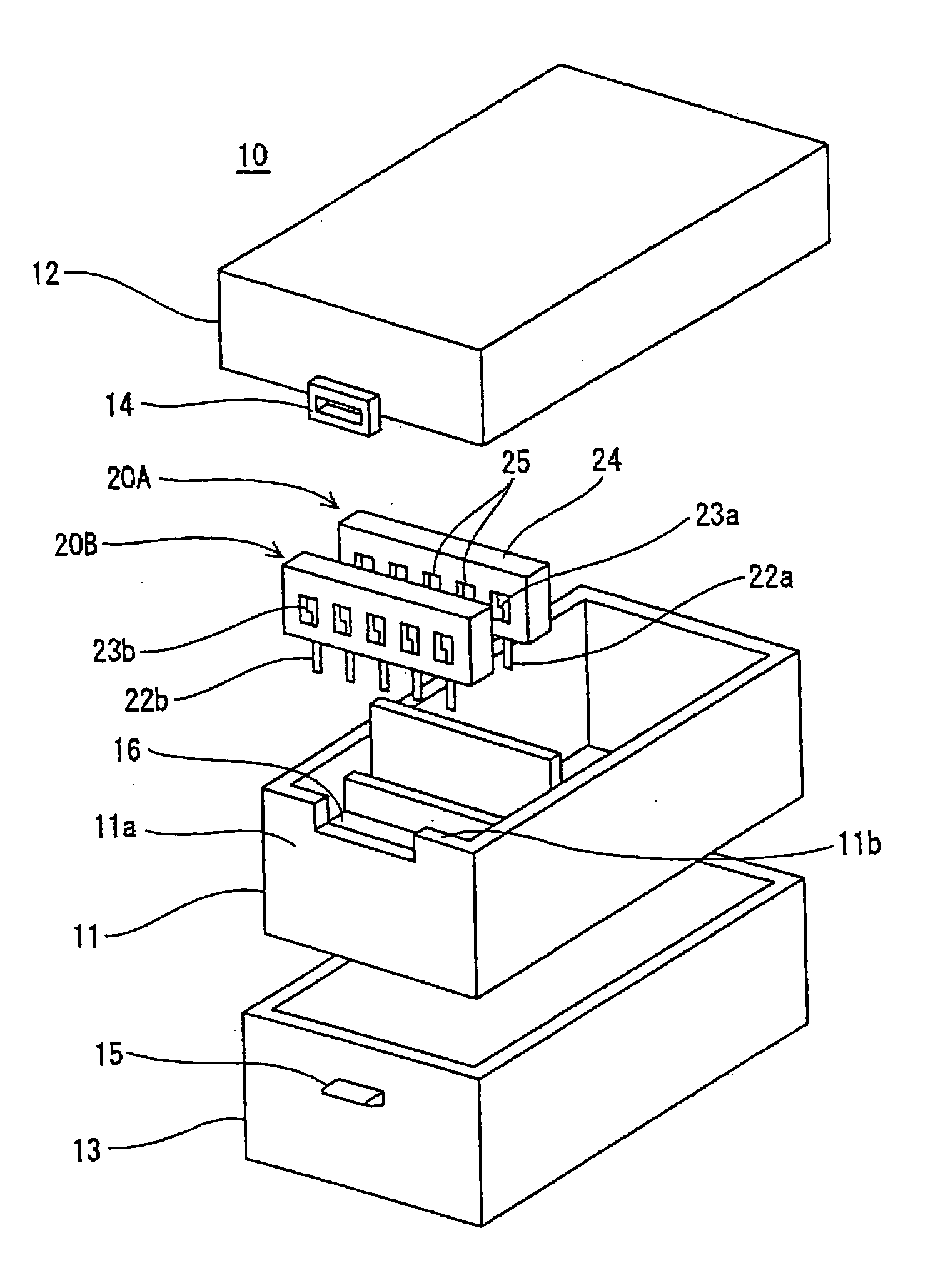
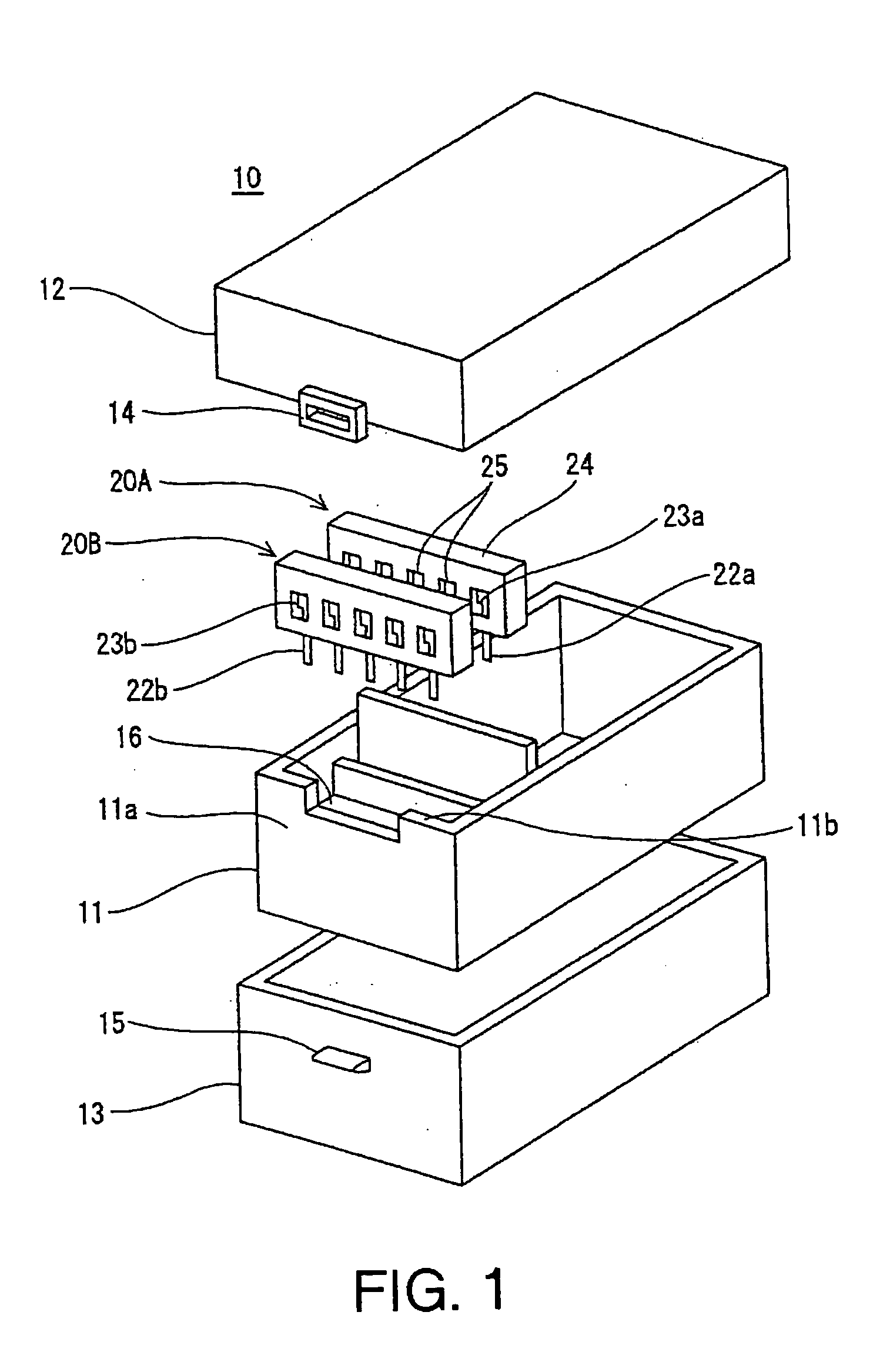
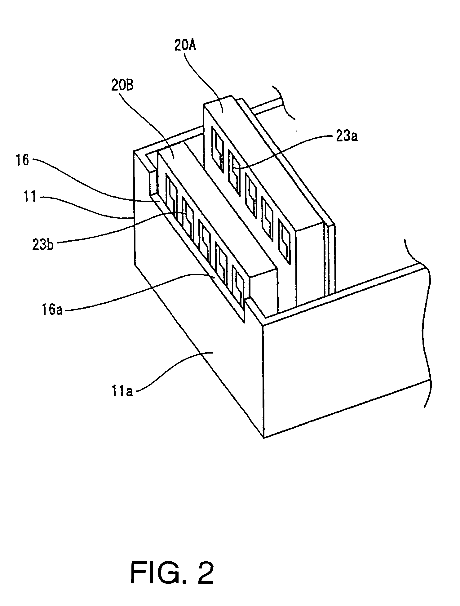
[0022] Details of the present invention are described below with reference to the figures. FIGS. 1 through 3 depict an electrical connection box 10 of the first embodiment of the present invention. In this configuration, electrical connection box 10 houses two bus bars 20A, 20B in the case 11. The bus bars 20A, 20B include i...


PUM


Abstract

An electrical connection box has a configuration in which fuse sections of bus bars integrated with fusible links housed in parallel alignment can be visually inspected with ease. The bus bars are positioned with space therebetween so that a bus bar closest to a peripheral wall of the case is placed at a lowest position and that the inner bus bars are placed at higher positions. A cut-out section is provided on an upper edge of a peripheral wall of the case so that the position of the cut-out section opposes the fuse sections of the bus bar at the lowest position.

Description

BACKGROUND OF THE INVENTION [0001] 1. Field of the Invention [0002] The present invention relates to an electrical connection box, and more particularly, to an electrical connection box in which a plurality of bus bars integrated with fusible links are provided in parallel alignment such that determination of blown fuse sections may be confirmed from outside the case with ease. [0003] 2. Description of the Background Information [0004] As FIG. 6 illustrates, electrical connection boxes mounted on automobiles may house bus bars integrated with fusible links 1. The bus bars may be manufactured by stamping out a piece of bus bar 2, and integrally providing fuse sections 5. The fuse sections 5 include a plurality of narrow sections, each located between one of a plurality of output terminals 4 and input terminal 3 connected to a battery. An example of a known bus bar is described in Japanese Patent Application Publication No. 2002-52433. [0005] A bus bar 1 with the above configuration m...

Claims


Application Information

Patent Timeline
IPC IPC(8): H01R12/00H02G3/16
CPCH01H85/2045H01H85/30H02G3/16H01H2085/208H02G3/086H01H2085/0555
Inventor ITO, KATSUYA
Owner SUMITOMO WIRING SYST LTD
Why Eureka
Try Eureka