Contact structure, an apparatus having the contact structure and image input apparatus having the contact structure

Active Publication Date: 2005-01-27
RICOH KK
View PDF11 Cites 15 Cited by
  • Summary
  • Abstract
  • Description
  • Claims
  • Application Information

AI Technical Summary

Benefits of technology

[0010] The present invention advantageously provides a contact structure that can decrease useless wiring resistance that is based on the contact terminal member, and can supply electricity having substantially the same voltage as the original voltage of the connection object, by means of effectively applying a bypassing conductive member having high electro conductivity in comparison with t

Problems solved by technology

However, the structures described in these documents cannot stably supply electricity having substantially the same voltage as the original voltage of the connection object, such as the battery and the AC adapter, so that stable contact pressure cannot be held and cannot reduce contact resistance.
Namely, there is a problem that extremely lower voltage than original voltage supplied by the battery is supplied since a length from the

Method used


Image

  • Contact structure, an apparatus having the contact structure and image input apparatus having the contact structure
  • Contact structure, an apparatus having the contact structure and image input apparatus having the contact structure
  • Contact structure, an apparatus having the contact structure and image input apparatus having the contact structure

Examples


Example

[0029] (First Embodiment)

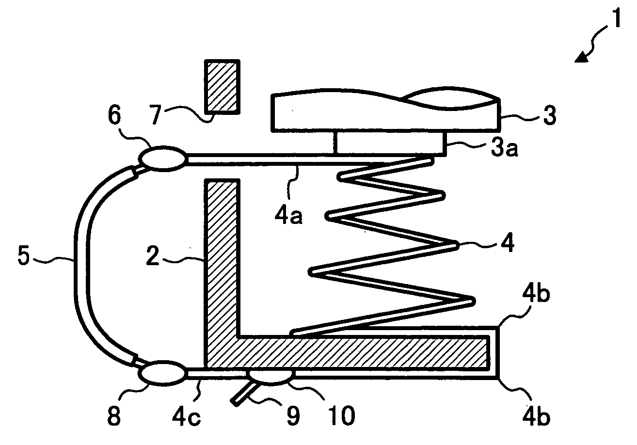
[0030]FIG. 1 is a front view of a contact structure 1 applied to an apparatus related to a first embodiment of the present invention. This contact structure 1 is applied to a battery housing of an image input apparatus such as a digital camera, for instance.

[0031] In FIG. 1, the contact structure 1 has a battery housing 2 arranged to house a battery 3 as a predetermined connection object. The battery housing 2 has a spring 4 that is arranged within an inside of one end side of the battery housing 2 as a contact terminal member in order to urge the battery 3 toward another end side within the inside of the battery housing 2. The spring 4 has a movable side end 4a and a fixed side end 4c at either end thereof. The fixed side end 4c of the spring 4 is fixed to one end side of the battery housing 2. The movable side of the spring 4 is configured to contact the battery 3 as the connection object. The movable side end 4a of the spring 4 is extended from a contac...

Example

[0036] (Second Embodiment)

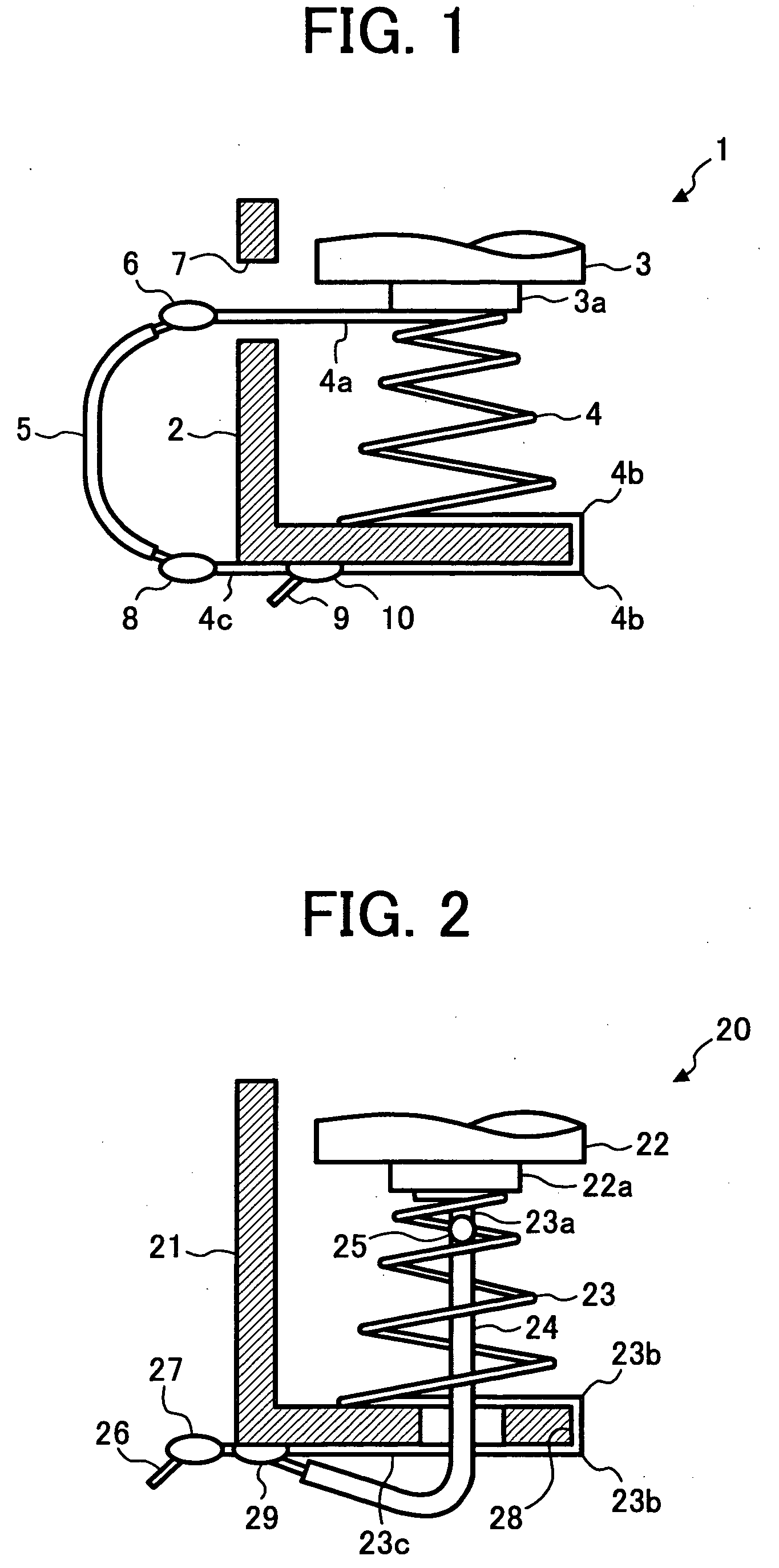
[0037]FIG. 2 is a front view of a contact structure 20 applied to an apparatus related to a second embodiment of the present invention. This contact structure 20 is applied to a battery housing of an image input apparatus such as a digital camera, for instance.

[0038] In FIG. 2, a contact structure 20 has a battery housing 21 arranged to house a battery 22 as a connection object. The battery housing 21 has a spring 23 that is arranged in an inner portion of one end side of the battery housing 21 as a contact terminal member in order to urge the battery 22 toward the other end side of the inner portion of the battery housing 21. The spring 23 has a movable side end 23a and a fixed side end 23c at ends thereof. A fixed side end 23c of the spring 23 is fixed to one end side of the battery housing 21. The movable side end 23a of the spring 23 is configured to contact to the battery 22 as the connection object. The movable side end 23a of the spring 23, as a fl...

Example

[0046] (Third Embodiment)

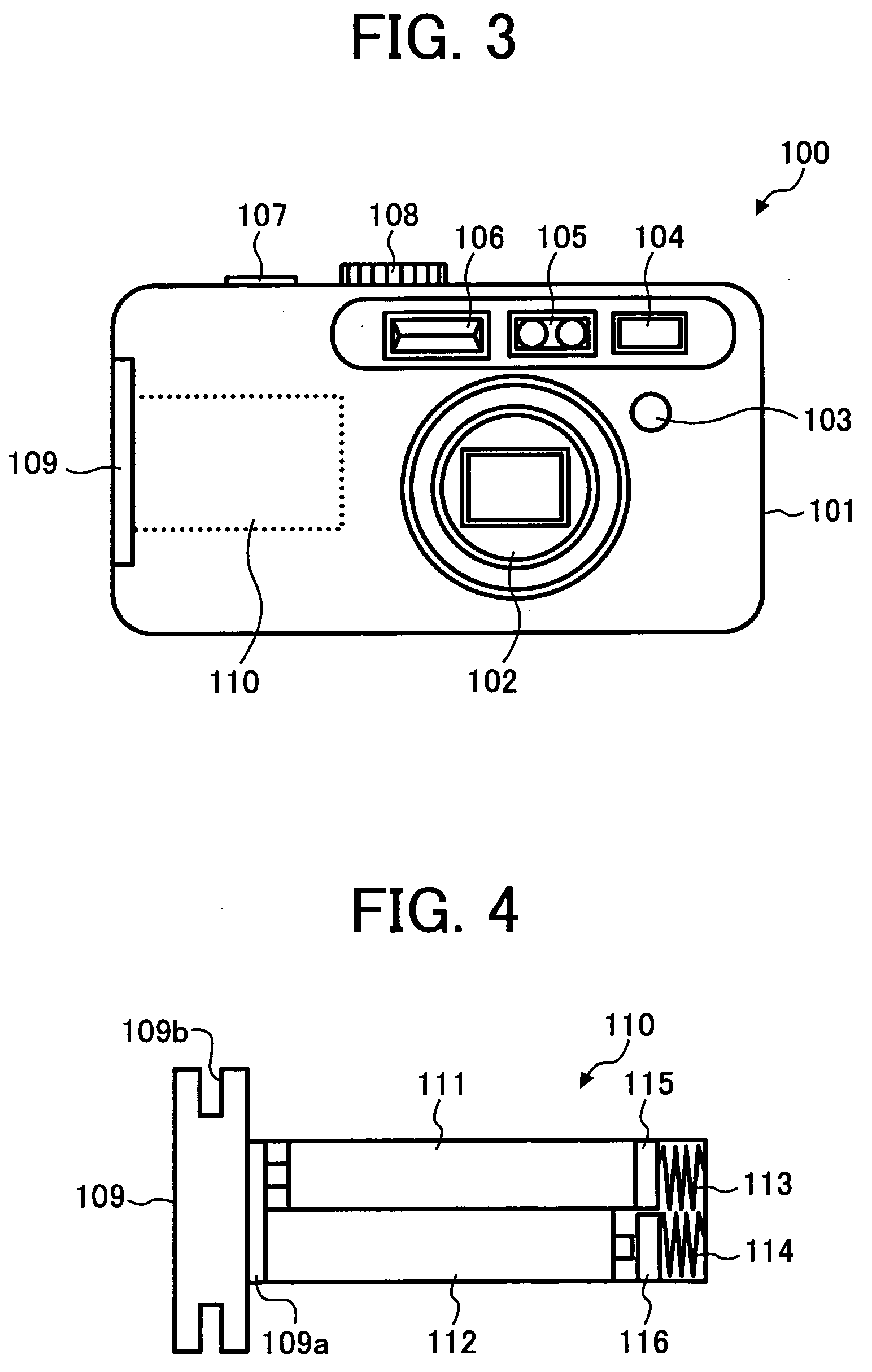
[0047]FIG. 3 is an external view of a digital camera 100 related to a third embodiment of the present invention. The digital camera 100 has a lens barrel unit 102, a wireless remote control signal receiver 103, an optical finder 104, a range finder 105 and a stroboscope 106 arranged on a front side of the body 101. A shutter release switch 107 and a mode dial 108 are arranged on top of the digital camera 100. And, a card / battery lid 109 is arranged on a lateral face of the digital camera 100.

[0048] The lens barrel unit 102 is configured to receive a lens group. The wireless remote control signal receiver unit 103 is configured to receive a signal from a wireless remote control unit operated by a user. The optical finder 104 is configured to view the subject in order to decide a shooting angle. The range finder 105 is configured to measure a distance to the subject. The stroboscope 106 is configured to emit light to light up the subject. The shutter release...


PUM


Abstract

A contact structure having a spring with electro conductivity. The spring is fixed at one inner end side of a battery housing by engaging a plurality of inflection parts of the spring to one end side of the battery housing. The spring urges the battery to the other end side of a battery housing. An end portion on movable side end of the spring is extended toward an opening on a lateral face of the battery housing. The end portion is formed on a contact side end of the spring that is contacted with the battery, and is connected to one end side of a bypassing lead wire. An end portion on the fixed side end of the spring is connected to the other end side of the bypassing lead wire. The end portion of the fixed side end of the spring is connected to a power source lead wire.

Description

BACKGROUND OF THE INVENTION [0001] 1. Field of the Invention [0002] The present invention relates to a contact structure, an apparatus having the contact structure and an image input apparatus having the contact structure. The contact structure can electrically contact to a predetermined connection object stably using a bypassing conductive member with less contact resistance. [0003] 2. Description of the Related Art [0004] Apparatuses that are driven by means of a battery are generally known. In particular, such devices include digital cameras, film cameras, compact disk players, radios, wireless remote control transmitters and various communication instruments. These apparatuses have a battery housing arranged to detachably house a battery. The battery housing has a contact terminal member configured to stably hold the battery by facing the electrode of the battery that is housed, and has a resilient contact terminal member configured to urge the battery into the contact terminal ...

Claims


Application Information

Patent Timeline
IPC IPC(8): G03B17/02H01R4/48H01M2/10H01M2/20
CPCG03B17/02H01M2/204H01M2/1022Y02E60/10
Inventor SHINOHARA, JUNICHITSURUKAWA, IKUYAMIYOSHI, AKEMIYOKOYAMA, KOUJI
Owner RICOH KK
Why Eureka
Try Eureka