Networked control system with real time monitoring

a networked control and monitoring system technology, applied in the field of networked control and monitoring systems, can solve the problems of little or no configurability of the various components

Inactive Publication Date: 2005-01-27
ROCKWELL AUTOMATION
View PDF6 Cites 28 Cited by
  • Summary
  • Abstract
  • Description
  • Claims
  • Application Information

AI Technical Summary

Benefits of technology

[0005] The present invention provides a real time monitoring approach for industrial control applications designed to respond to these needs. The approach makes use of components which are adapted to either control or monitor operational parameters of the system, including application of electrical power to loads such as motors. Programmable components include memory objects which are dedicated to storing specific types of information, such as system designation, component designation, component function, component location, and so forth. Based upon the stored data from each component, and upon sensed data from the component, a monitoring station accesses information via a data network and compiles user viewable representations of monitored data. The user may configure the data in various ways, depending upon preferences and any defaults which may be associated with the particular components.

Problems solved by technology

However, such systems still typically rely upon dedicated readout devices which are adapted to provide visual indications of parameter levels, with little or no configurability for the various components of the networked system.

Method used


Image

  • Networked control system with real time monitoring
  • Networked control system with real time monitoring
  • Networked control system with real time monitoring

Examples


Embodiment Construction

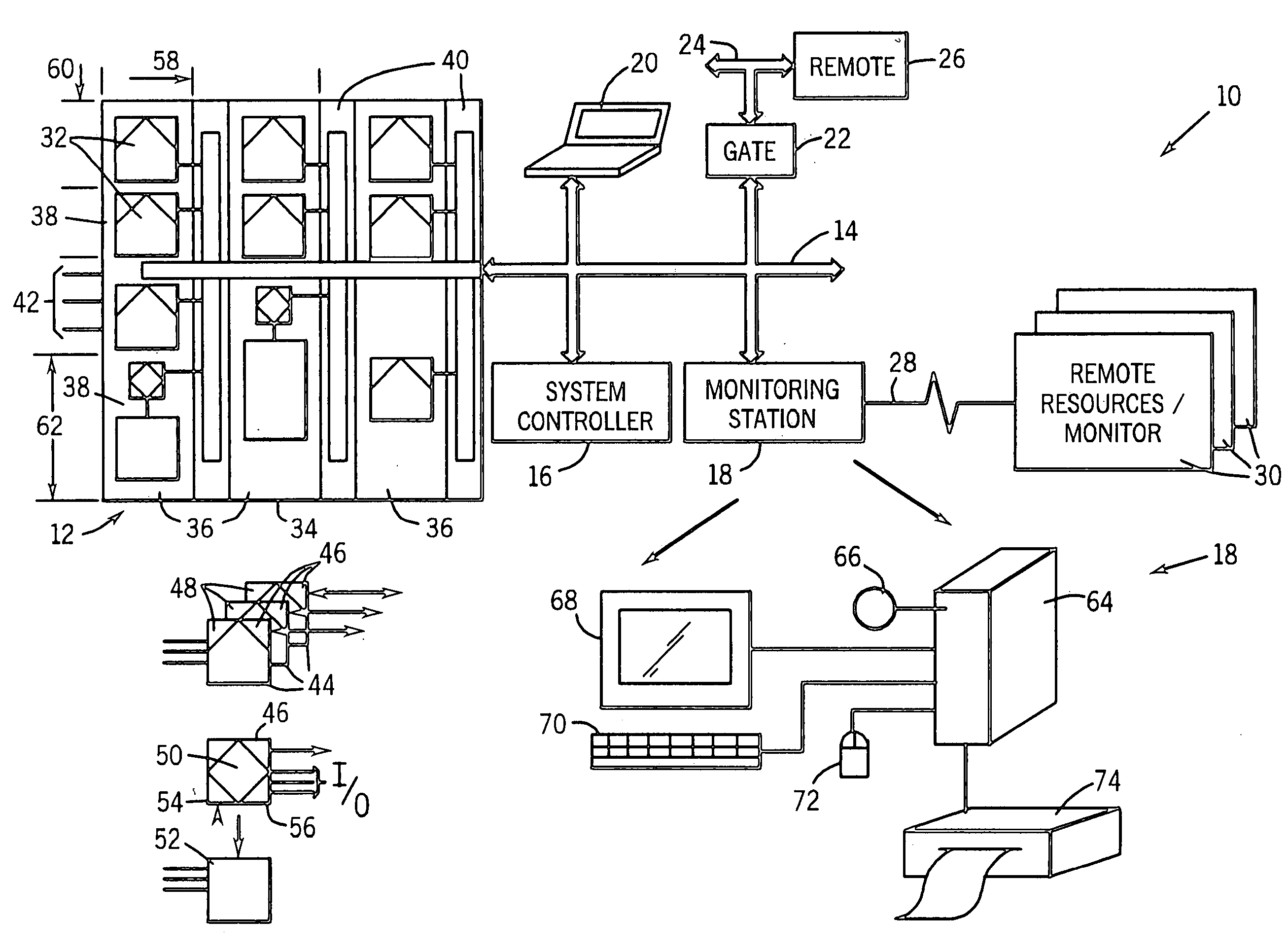
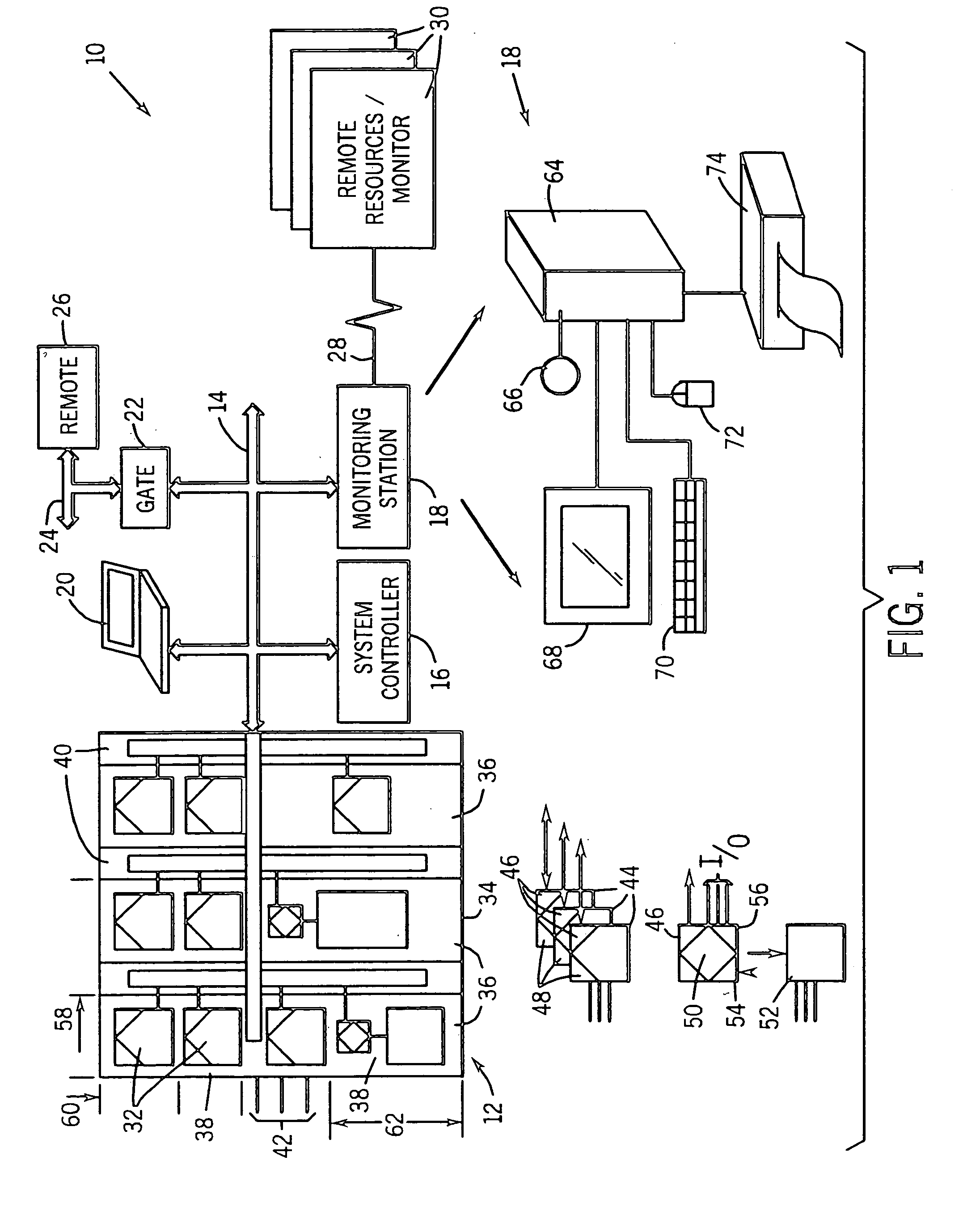
[0022] Turning now to the drawings, and referring first to FIG. 1, a control and monitoring system 10 is illustrated as including a component assembly 12, and a network 14 for transmitting data to and from components of the assembly. While the component assembly 12 may take many forms, and include devices for accomplishing many different and varied purposes, in a preferred implementation, the component assembly includes electrical control and monitoring equipment for regulating application of electrical power to loads. In particular, the components may include motor starters, motor controllers, variable frequency drives, relays, protective devices such as circuit breakers, programmable logic controllers, and so forth. In the industrial automation field, such component assemblies are commonly referred to as motor control centers (MCC's).

[0023] In addition to the component assembly and network, system 10 includes a system controller 16 and a monitoring station 18. System controller 1...


PUM


Abstract

A technique for monitoring operational parameters of networked components includes storing data within each component descriptive of the component. The data is polled by a monitoring station and provides a basis for monitor views compiled in real time. The monitor views provide a view of current levels of parameters controlled or monitored by each device, such as on virtual meters. Historical levels of operational parameters may be presented in virtual strip chart output. Textual descriptions of the components are provided, along with listings of key settings. More detailed data may be accessed by links between the monitor views and other user viewable representations for the system and the specific components.

Description

BACKGROUND OF THE INVENTION [0001] The present invention relates generally to the field of networked control and monitoring systems, such as those used in industrial automation applications. More particularly, the invention relates to a technique for conducting real time monitoring operations in a control and monitoring system, to display information for a user based upon data collected in real time and descriptive of both operational parameters and particular components and their individual configurations. [0002] A wide range of systems are known and have been developed for conducting local and remote monitoring operations in industrial control applications. In conventional systems, gages, meters, and the like were situated at specific locations corresponding to loads to which electrical power was applied. Such loads might include electric motors, valves, actuators, and so forth. Data is collected from the monitoring equipment by visual inspection. Such monitoring devices have also...

Claims


Application Information

Patent Timeline
Patent Type & Authority Applications(United States)
IPC IPC(8): G06F11/30G06F15/00H04L29/06
CPCH04L63/1408
Inventor RETLICH, KEVIN A.LUO, JINGHUIBLAIR, DAVE D.
Owner ROCKWELL AUTOMATION
Why Eureka
Try Eureka