
Control server and remote control system for the same

a control server and remote control technology, applied in the field of remote control systems, can solve the problems of unable to identify each of the remote control terminals, unable to control exclusive control from a plurality of remote control terminals through the control server, and unable to block viewing

Inactive Publication Date: 2005-01-27
NEC CORP
View PDF15 Cites 19 Cited by
  • Summary
  • Abstract
  • Description
  • Claims
  • Application Information

AI Technical Summary

Benefits of technology

[0033] Therefore, an object of the present invention is to provide a remote control system, and a control server used in it, in which it is possible to carry out exclusive remote control of a control object terminal appropriately from each of remote control terminals when the remote control terminals exist in remote control of control object terminal with a 1394 interface.

Problems solved by technology

At this time, a problem of obstruction of the viewing occurs.
However, there are the following problems in the conventional technique when the above-mentioned control server and the remote control terminal are connected through the network.
First, in the conventional remote control system, there is a problem that an exclusive control from a plurality of remote control terminals through the control server is impossible.
However, in the conventional exclusive control, it is impossible to identify each of the remote control terminals and the exclusive control among the remote control terminals is impossible.
Second, in the conventional remote control system, there is a problem that the exclusive control for each of a plurality of applications is impossible.
In other words, in the exclusive control using the conventional control right, there is a problem that the plurality of application programs can not be identified in addition to the first problem when the plurality of application programs exist in the control terminal.
There is a same problem as the above in case of the control of the control object terminal from the application programs of each control terminal in the 1394 network, in addition to the control from the remote control terminal.
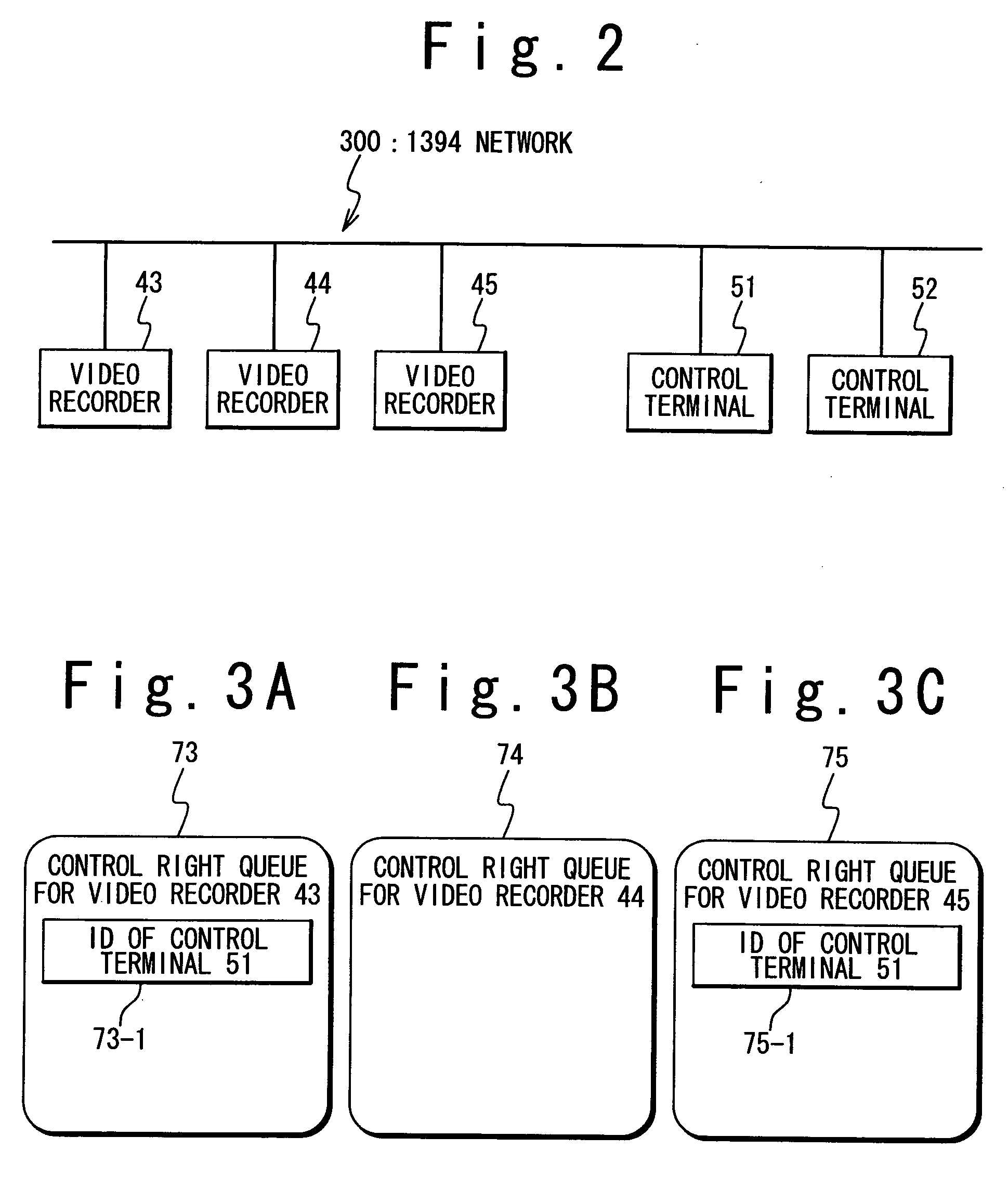
Third, even if the above-mentioned problem has been solved, a new problem arises that the control object terminal which is controlled by one of the application programs can not be controlled by another application program while the same user intends to control the control object terminal using the application programs, because a function is not provided to individually identify the controls of the control object terminal from the plurality of remote control terminals and the plurality of application programs.
Fourth, in the conventional remote control system, the exclusive control could not be reserved.
Fifth, in the conventional remote control system, convenience is lost when a plurality of control servers exist.

Method used


Image

  • Control server and remote control system for the same
  • Control server and remote control system for the same
  • Control server and remote control system for the same

Examples


first embodiment

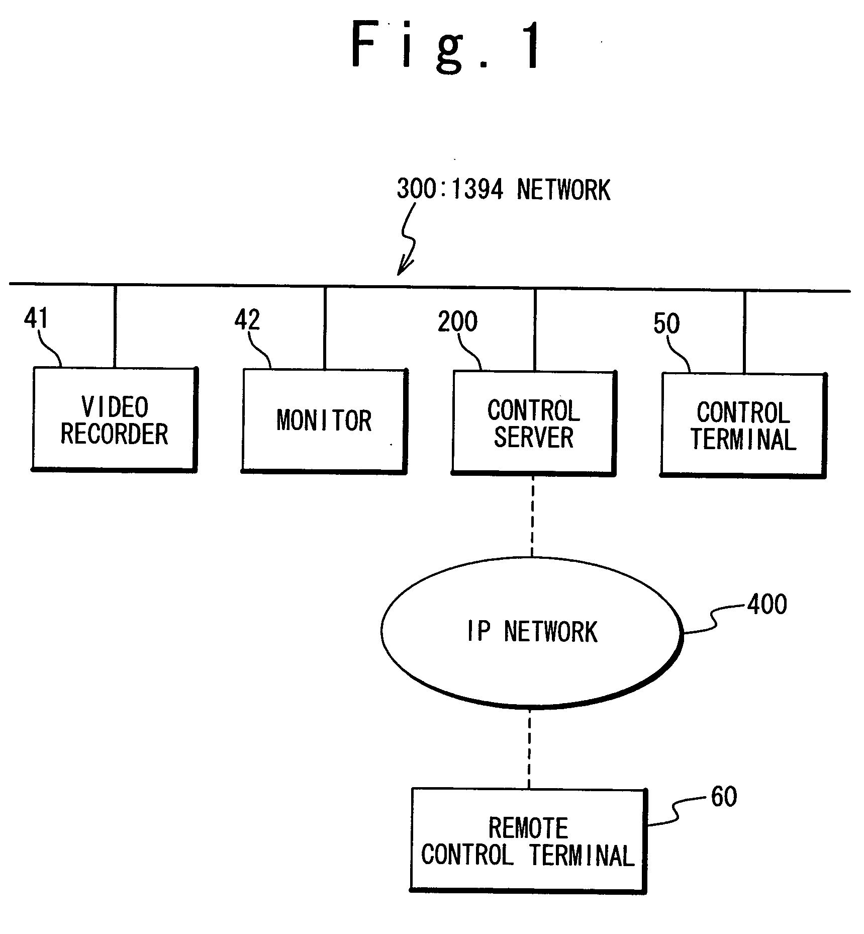
[0106]FIG. 6 is a block diagram showing an example of a network configuration of the remote control system according to the present invention. Referring to FIG. 6, in the network configuration, there are two kinds of networks of a 1394 network 300 and an IP network 400 as a network other than the 1394 network such as an Ethernet.

[0107] Also, the remote control system of the first embodiment is composed of a plurality of control object terminals 20-1 to 20-3 connected with the 1394 network 300, a control server 100 connected with both of the 1394 network 300 and the IP network 400 and a plurality of remote control terminals 10-1 to 10-3 connected with the IP network 400.

[0108] In FIG. 6, each of the 1394 network 300 and the control server 100 exists for only one but actually, a plurality of 1394 networks and a plurality of control servers may exist. Also, in FIG. 6, three control object terminals 20-1 to 20-3 and three remote control terminals 10-1 to 10-3 are shown, but the number ...

third embodiment

[0155] In the third embodiment, the remote control terminal which has the remote control right of the control object terminal can set a password for the sharing of the remote control right for every control object terminal. This password may be specified by the user through a user interface and may be automatically generated by the remote control terminal.

[0156] When sharing the remote control right is wanted, the remote control terminal can request the sharing of the remote control right by showing the password to the control server 100. The sharing of the remote control right is permitted when this password is coincident with a preset password and the permitted one of the remote control terminals 10-1 to 10-3 can control the control object terminals 20-1 to 20-3 like the remote control terminal which has the remote control right. Also, a connection release right can be shared by using the password like the remote control right.

[0157] Next, the operation of the third embodiment wi...

fourth embodiment

[0164] In the fourth embodiment, when the remote control terminal 10-1 reserves a recording operation of the control object terminal 20-2, it is possible to request to secure the remote control right previously until a recording end time. For example, when the securing of the remote control right and the connection release right are requested until time 23:00, the remote control right management table 151c and the connection management table 152c become shown in FIGS. 24 and 25. In this case, even if the remote control terminal 10-1 ends the communication with the control server 100, the other remote control terminals 10-2 and 10-3 can not control the control object terminal 20-2 until 23:00. Also, because all of the remote control terminals 10-1 to 10-3 do not have the remote control right and the connection release right after 23:00, the remote control and the connection release become possible from all the remote control terminals 10-2 and 10-3 which are communicating with the co...


PUM


Abstract

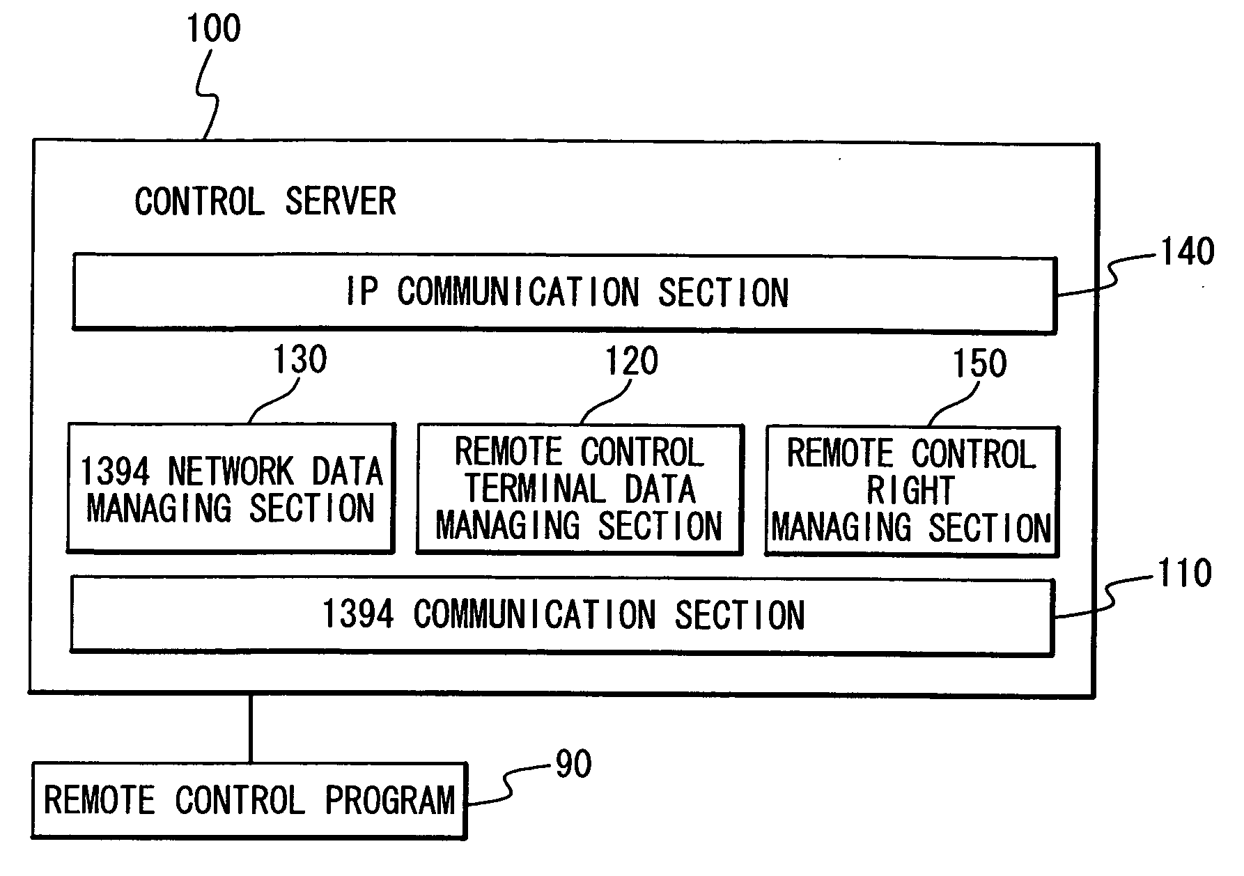
A remote control system includes a plurality of control object terminals connected with the first network, a control server connected the first network and a second network to control the control object terminal and a remote control terminal connected with the second network. The remote control terminal issues a control request for a specific terminal of the plurality of control object terminals to the control server through the second network. The control server identifies the remote control terminal uniquely in response to the control request and carries out the control request in place of the remote control terminal when the remote control right of the specific terminal is allocated to the remote control terminal.

Description

TECHNICAL FIELD [0001] The present invention relates to a remote control system which controls information home electronics terminals which are connected with IEEE 1394 network (IEEE Std 1394-1995; a high-speed serial bus standardized in IEEE Standard for a High Performance Serial Bus, and called 1394 network hereinafter), and a control server used in it. BACKGROUND ART [0002] First, the outline of a 1394 network and an exclusive control technique in the 1394 network will be described below. Also, problems of a conventional remote control in a 1394 network to which the present invention should be applied and problems when a conventional exclusive control technique is applied to the conventional remote control technique will be described. [0003] In the 1394 network, a synchronous transfer mode and an asynchronous transfer mode are prescribed as data transfer modes. The synchronous transfer mode is used for signal transmission and reception in applications such as video image data and...

Claims


Application Information

Patent Timeline
Patent Type & Authority Applications(United States)
IPC IPC(8): H04L12/12G06F13/00H04L12/46H04Q9/00
CPCY02B60/34H04L12/12Y02D30/50
Inventor NAKAJI, HIROSHI
Owner NEC CORP
Learn More