Connector for a solar module

a solar module and connection plate technology, applied in the direction of coupling contact members, pv power plants, coupling device connections, etc., can solve the problems of complex production, high production cost, and the need for permanent connection of this type, and achieve the effect of reducing the total height of the contact pla

Inactive Publication Date: 2005-02-03
HARTING ELECTRIC GMBH & CO KG
View PDF13 Cites 42 Cited by
  • Summary
  • Abstract
  • Description
  • Claims
  • Application Information

AI Technical Summary

Benefits of technology

[0005] The invention is based on the objective of developing a connector of the initially described type in such a way that separable electric connections between the connecting lines of solar modules and electric service cables can be easily and inexpensively produced without requiring tools.
[0008] The advantages attained with the invention can be seen, in particular, in that the contact pins with a pyramid-shaped surface structure make it possible to realize a direct and gas-tight contact with the flat electric connecting lines that are arranged within the solar module and serve for electrically interconnecting the individual photovoltaic solar elements that are embedded in a sandwich panel.
[0010] In this context, it is particularly advantageous that the contact pins are held on a spring element and thusly exert a constant pressure upon the connecting lines such that excessive contact resistances are prevented.
[0012] The contact plate contains an integral base plate that is held between the sheets, wherein a collar-shaped connecting part of the contact plate makes it possible to produce a connection with a connector housing in a recess in one of the sheets by attaching the connector housing to the recess.

Problems solved by technology

The disadvantage of such an arrangement is that a permanent connection of this type needs to be soldered or welded and is quite complicated and expensive to produce.

Method used


Image

  • Connector for a solar module
  • Connector for a solar module
  • Connector for a solar module

Examples


Embodiment Construction

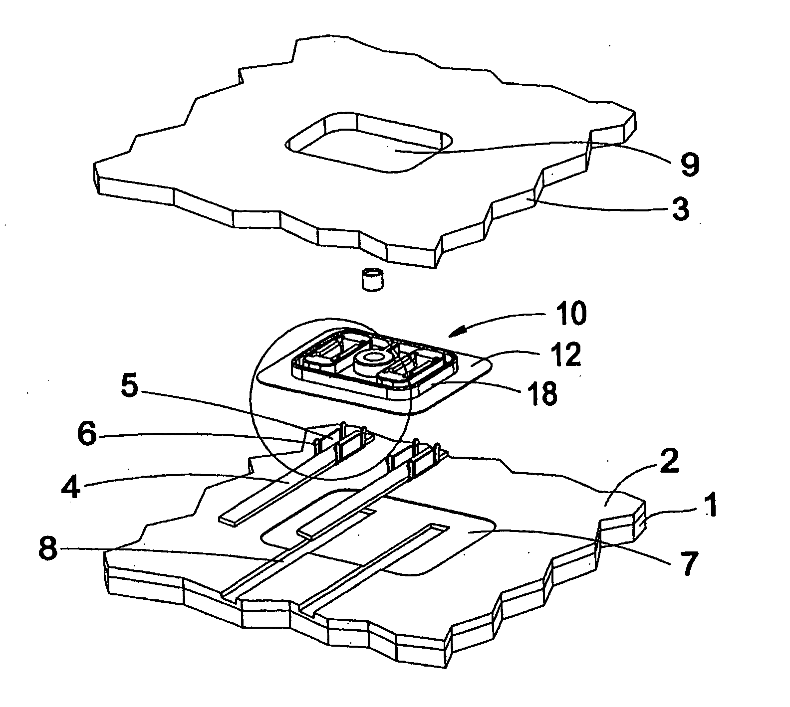
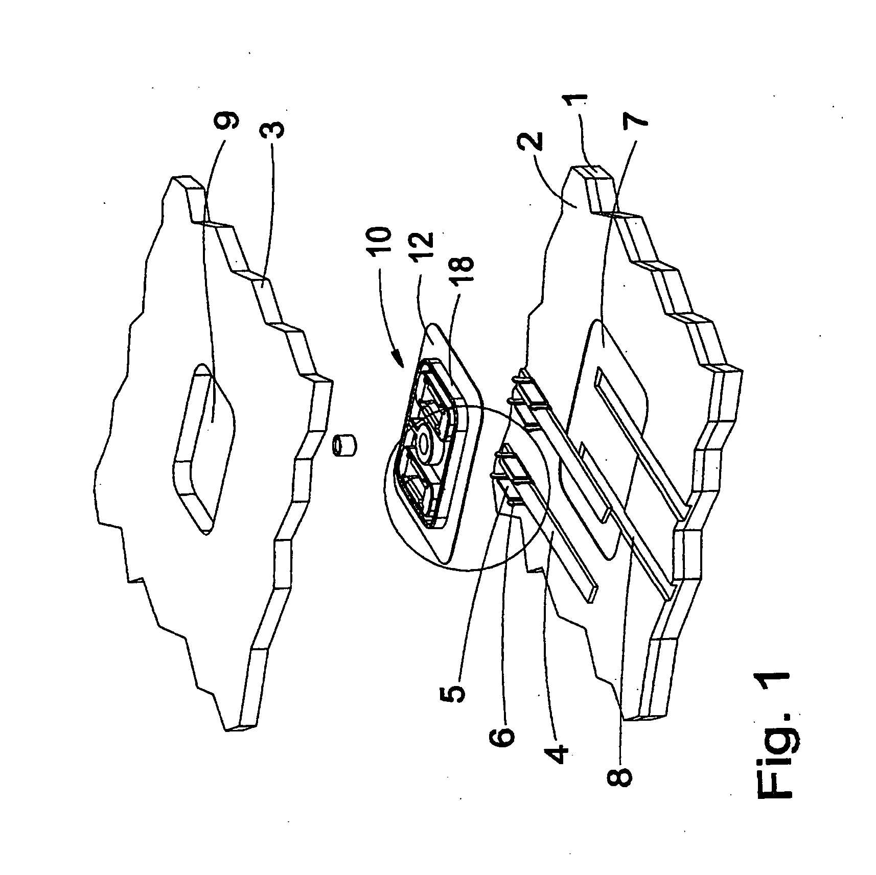
[0027]FIG. 1 shows a translucid sandwich panel of a solar module that consists of an outer sheet 1 and an inner sheet 3, between which a plastic layer 2 is arranged. Photovoltaic solar elements (not shown in the figure) are embedded in this plastic layer.

[0028] Flat connecting lines 4 lead from the solar elements to a central supply terminal, on which a contact plate 10 in the form of a flat housing part is arranged.

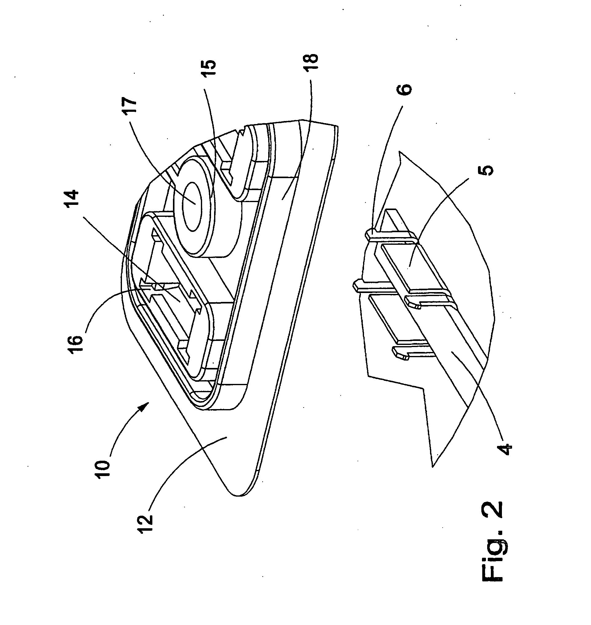
[0029] The connecting lines 4 are inserted into channels 8 in the plastic layer 2 and partially encompassed by reinforcing elements 5 on their ends. The contact plate 10 is realized in the form of a flat, rectangular part and comprises a base plate 12, on which a structure of different shapes is arranged and surrounded by a collar 18.

[0030] The contact plate is placed on the plastic layer 2 above the connecting lines 4, namely in a depression 7 that corresponds to the base plate. The catch means 6 provided on the reinforcing elements 5 respectively engage on an underc...


PUM


Abstract

In order to deliver the current generated by means of photovoltaic solar elements, the invention proposes a connector for a solar module that is accommodated in a connector housing and can be connected to the solar elements. The solar elements are interconnected by means of flat connecting lines and embedded in a translucid sandwich panel. The current is delivered through an opening in one of the sheets of the sandwich panel by means of springable contact elements that are in electric contact with the connecting lines of the solar elements.

Description

TECHNICAL FIELD [0001] The invention pertains to a connector for a solar module that is arranged in a connector housing and serves for connecting an electric service cable to electric connecting lines of the solar module that are arranged within translucid sandwich panels and serve for electrically interconnecting several photovoltaic solar elements. BACKGROUND OF THE INVENTION [0002] A connector of this type is required for delivering the solar electricity generated by photovoltaic solar elements in a solar module to a consumer via a service cable. [0003] A plate-shaped photovoltaic solar module with an outer plate and an inner plate, as well as a plastic layer with embedded solar cells, is known from EP 1 006 593 A1. The connector of this solar module consists of a plug-and-socket connector that is arranged in an opening in the inner plate and permanently connected to several connecting lines of the solar cells. BRIEF SUMMARY OF THE INVENTION [0004] The disadvantage of such an arr...

Claims


Application Information

Patent Timeline
Patent Type & Authority Applications(United States)
IPC IPC(8): H01L31/042H01R13/73H01L31/05H01R13/22H01R13/52
CPCH01R13/22H01R13/5205H01L31/02013H02S40/34Y02E10/50
Inventor NASS, ANDREASPOST, DIRK-PETERSCHMIDT, MARTINSORIG, LUDGERSTEIN, HARTWIG
Owner HARTING ELECTRIC GMBH & CO KG
Why Eureka
Try Eureka