Shape memory alloy-actuated and bender-actuated helical spring brakes

a technology memory alloys, applied in the direction of mechanical equipment, machines/engines, transportation and packaging, etc., can solve the problems of requiring substantial effort to release the helical wrap spring, the use of linkages and gears tends to limit the placement of triggers, and the use of helical spring brakes can be difficult for elderly or otherwise infirm users to manually separate the spring ends,

Inactive Publication Date: 2005-02-03
ALFMEIER PRAZISION BAUGRUPPEN & SYSTLOSUNGEN
View PDF2 Cites 63 Cited by
  • Summary
  • Abstract
  • Description
  • Claims
  • Application Information

AI Technical Summary

Problems solved by technology

But the conventional actuation mechanisms used to activate braking in these applications, although adequate in operation, are typically associated with one or more of the following drawbacks.
A first drawback is that conventional actuation mechanisms usually require either numerous quantities of members (e.g., a number of gears) or large-sized members (e.g., elongated activator members, such as rods or cables), or both, to effectuate actuation.
Other drawbacks of current helical spring brake actuators are that the use of linkages and gears tend to either limit the placement of a trigger for the actuator or require sufficient physical dexterity by users to trigger actuation (i.e., by manually separating the spring ends), or both.
As such, manual separation of the spring ends can be difficult for elderly or otherwise infirm users.
For example, automobile parking brakes or hood latches employing helical spring brakes generally require substantial effort to release the helical wrap spring.
Moreover, the triggering means to release parking brakes and hood latches, such as a knob, are inconveniently located underneath the steering wheel and dashboard.
An example of such a triggering means is a manual seat latch, which is inconveniently located at the bottom of a seat back, near the floor of a vehicle.
So, conventional actuation mechanisms generally limit designers from placing the triggering means in a convenient location.
Another drawback is that the mechanical linkages and gears that traditionally constitute these actuators can inadvertently generate audible sounds, as noise, from the interaction of the actuator components.

Method used


Image

  • Shape memory alloy-actuated and bender-actuated helical spring brakes
  • Shape memory alloy-actuated and bender-actuated helical spring brakes
  • Shape memory alloy-actuated and bender-actuated helical spring brakes

Examples


Embodiment Construction

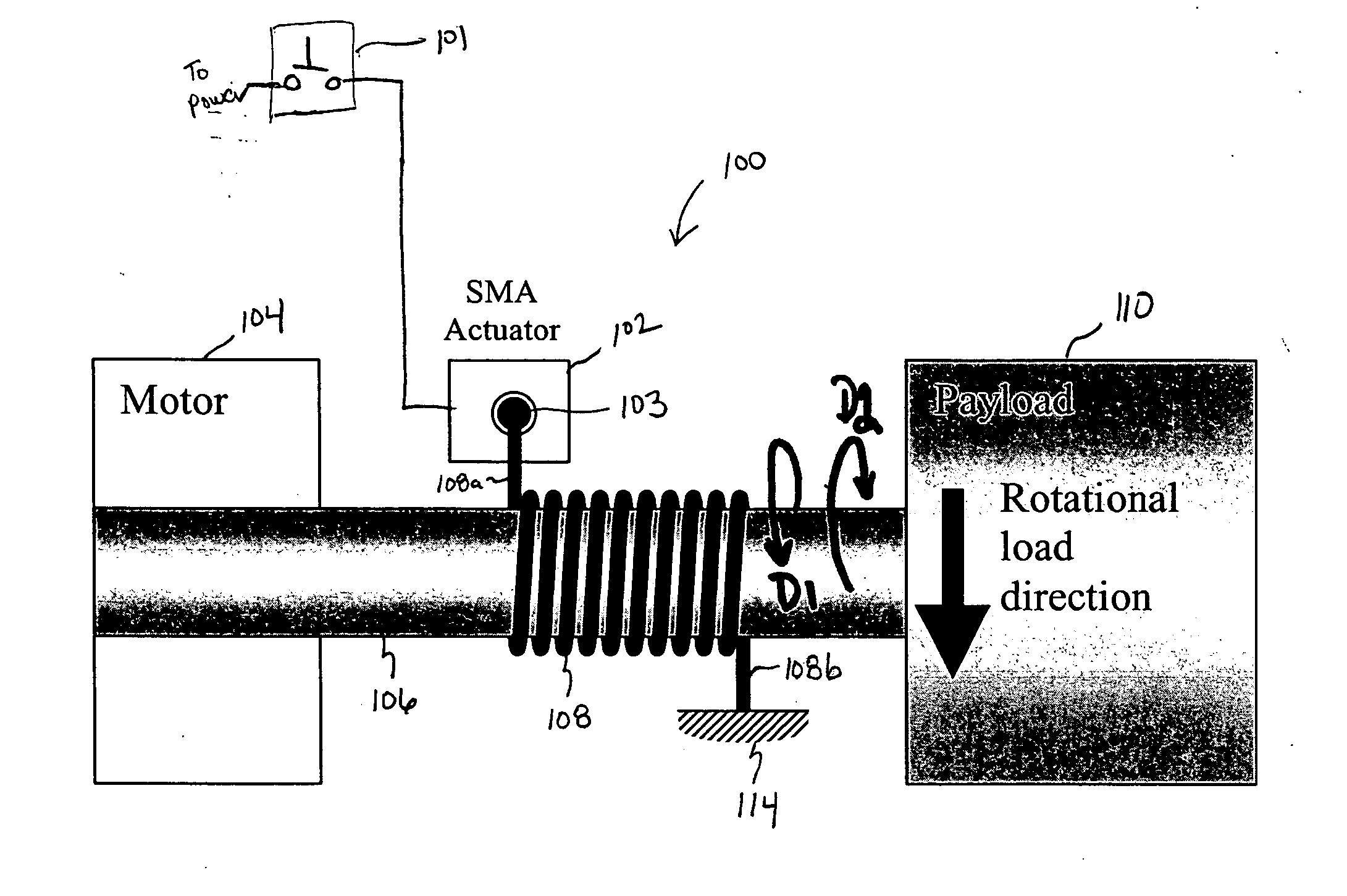
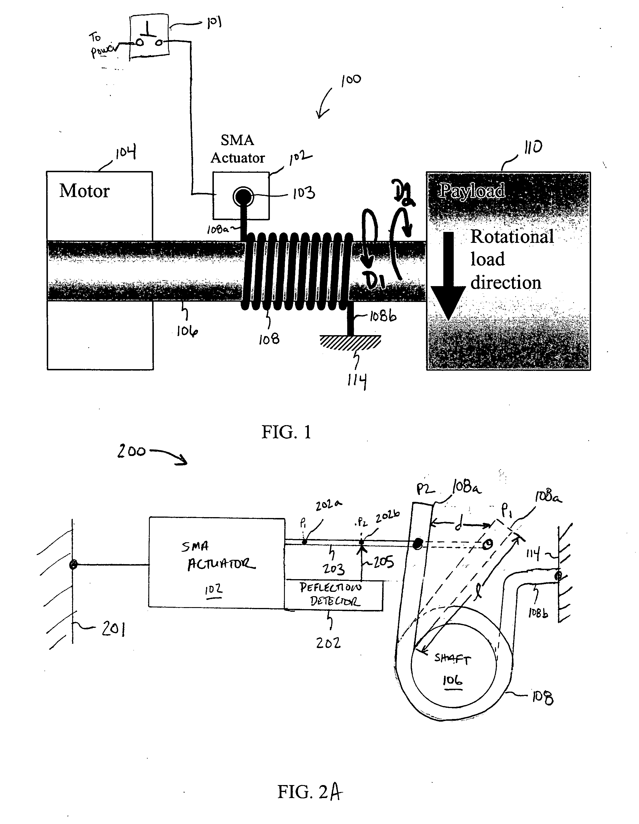
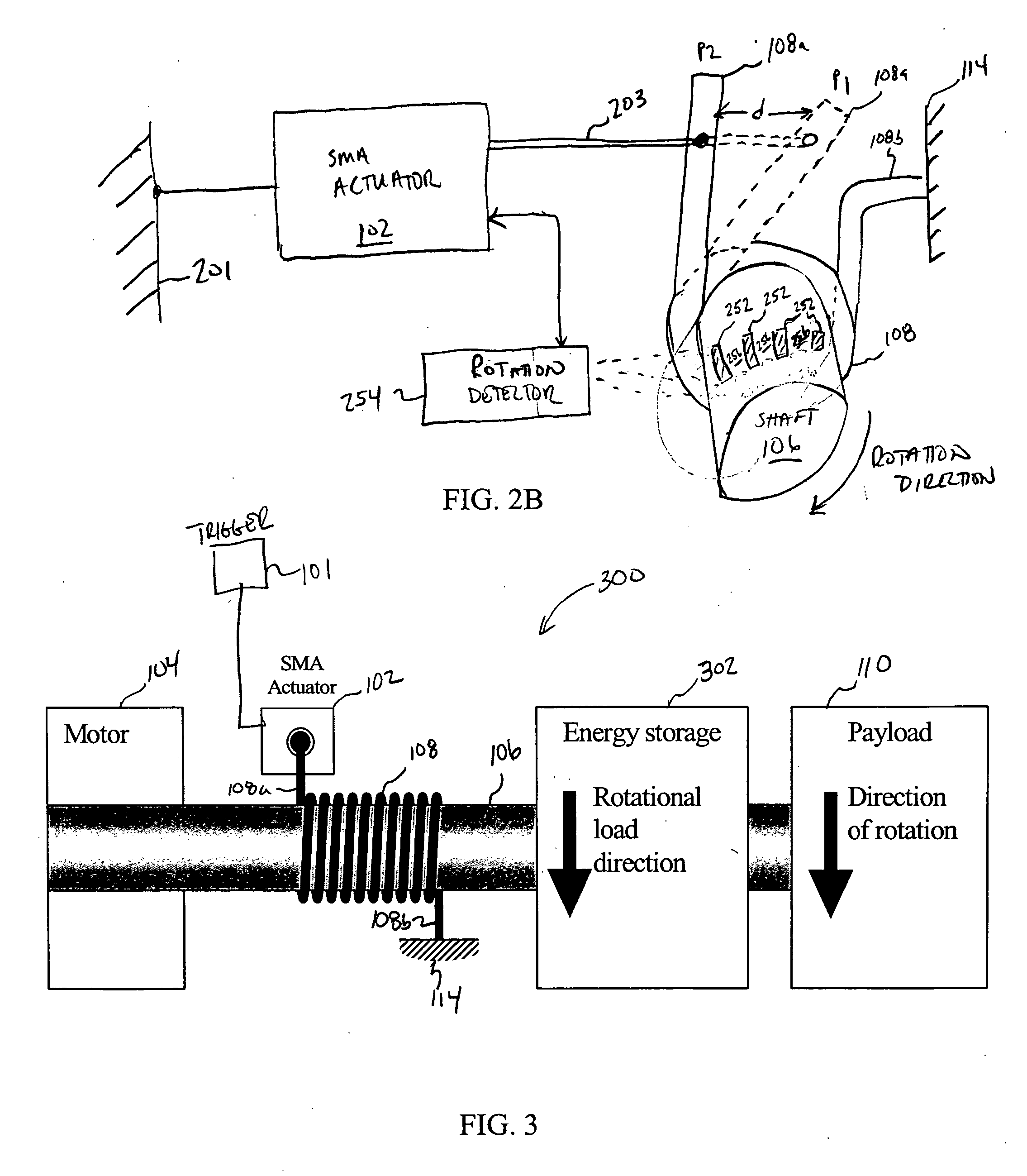
[0021] Embodiments of the present invention relate to SMA-actuated and bender-actuated helical spring brakes for imparting motion to a payload. According to some embodiments of the invention, an SMA-actuated helical spring brake can be configured to permit or inhibit a rotatable member to move a payload, such as window, a seat back, etc. Advantageously, an SMA-actuated helical spring brake according to some embodiments of the present invention can be formed with a relatively compact form factor so as to preserve space that otherwise would be consumed by sophisticated linkages, gears or other relatively complicated mechanical configurations. As such, embodiments of the present invention facilitate the miniaturization of helical spring brake actuator mechanisms. Without the need for physical efforts to release a helical spring brake in accordance to some embodiments, SMA-actuated helical spring brakes facilitate actuation for elderly and infirm users. Also, an SMA-actuated helical spr...


PUM


Abstract

In one embodiment of the present invention, a shape memory alloy (“SMA”)-actuated helical spring brake comprises a rotatable member and a helical wrap spring arranged concentrically about the rotatable member. The spring has a first spring end and a second spring end and includes a number of turns that are based radially inward and are configured to frictionally engage the rotatable member. The turns permit rotation of the rotatable member in a first direction and inhabit rotation in a second direction. The SMA-actuate helical spring brake also include an anchor point coupled to the second spring end, and an SMA actuator having an output drive member coupled to the first spring end. The SMA actuator is configured to, for example, deflect the first spring end to permit the rotatable member to rotate.

Description

CROSS REFERENCE TO A RELATED APPLICATION [0001] This application claims benefit under 35 U.S.C. 119(e) of United States Provisional Patent Application Number 60 / 484,021 filed Jun. 30, 2003 entitled “SMA-Actuated Helical Spring Brake,” the disclosure of which is incorporated herein by reference in its entirety.FIELD OF THE INVENTION [0002] The present invention relates generally to braking systems, and in particular, to shape memory alloy (“SMA”)-actuated and to bender-actuated helical brake mechanisms for permitting and inhibiting movement of one or more members relative to each other. BACKGROUND OF THE INVENTION [0003] Helical wrap springs are commonly employed in conventional braking mechanisms to control whether two or more moveable members can move relative to each other. In a typical helical spring brake, a helical wrap spring is positioned concentrically about, and in frictional engagement with, the outer surface of a drive member, such as a shaft or drum. The direction of the...

Claims


Application Information

Patent Timeline
Patent Type & Authority Applications(United States)
IPC IPC(8): B65H59/10F03GF03G7/06F16D49/02F16D51/00F16D55/02F16D65/14
CPCF03G7/065F16D2127/004F16D2121/32F16D49/02
Inventor SZILAGYI, ANDREI
Owner ALFMEIER PRAZISION BAUGRUPPEN & SYSTLOSUNGEN
Why Eureka
Try Eureka