
Filter piston apparatus for dispensing pulverulent bulk material

a filter piston and bulk material technology, applied in liquid dispensing, liquid/fluent solid measurement, contracting/expanding measuring chambers, etc., can solve the problems of high outlay, difficult access, and affect the metering accuracy of this dispensing apparatus, so as to keep the level of deformation of axially elastic filter medium low

Active Publication Date: 2005-02-03
HARRO HOFLIGER VERPACKUNGSMASCHEN
View PDF7 Cites 20 Cited by
  • Summary
  • Abstract
  • Description
  • Claims
  • Application Information

AI Technical Summary

Benefits of technology

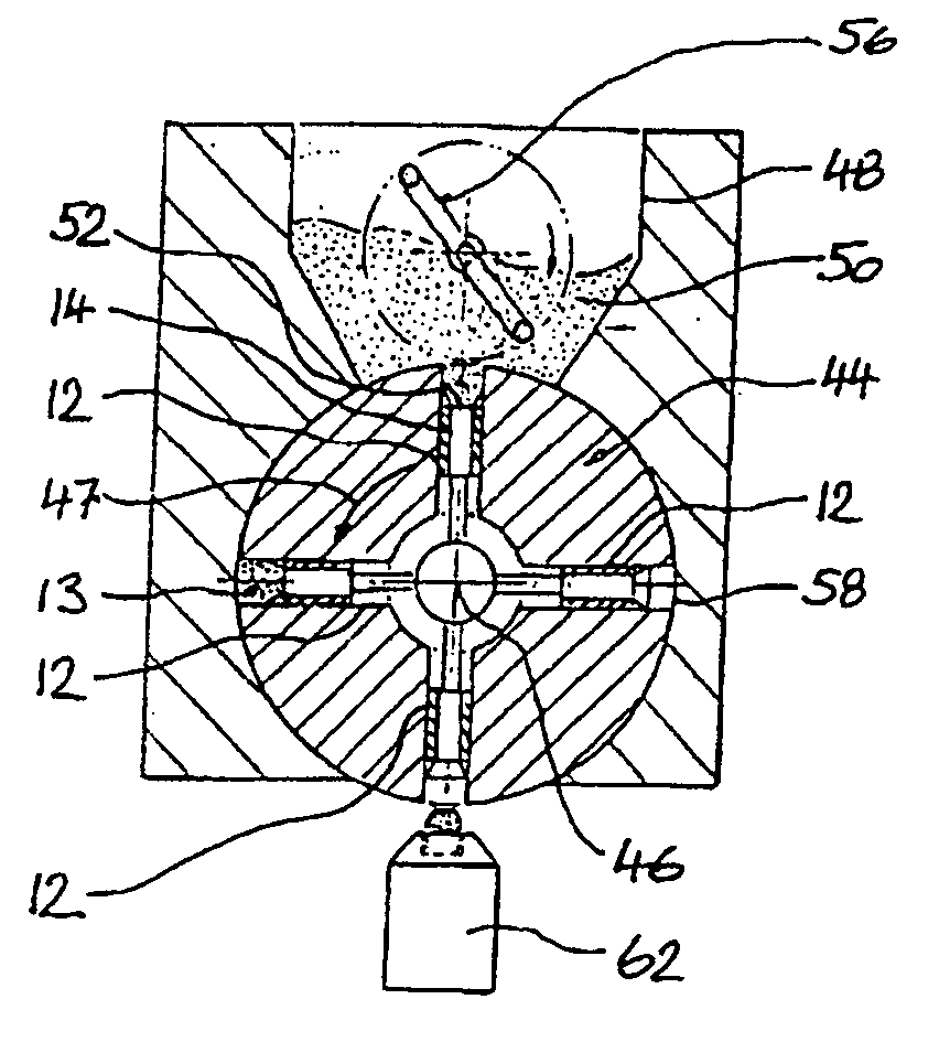
[0011] Taking this prior art as the departure point, the object of the invention is to specify a filter piston apparatus for dispensing pulverulent bulk material which allows, as far as possible, constant quantities of pulverulent bulk material to be dispensed. Nevertheless, this filter piston apparatus is to be capable of being operated as cost-effectively as possible.
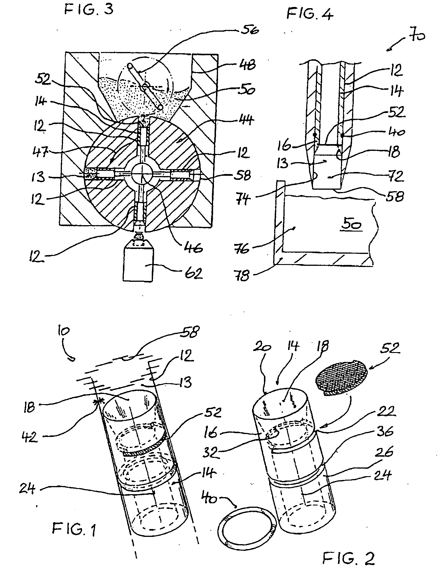
[0013] The filter piston apparatus according to the invention has a comparatively small number of components, which are of straightforward configuration. By virtue of the piston being plugged to different extents into the circular-cylindrical bore provided for it, the size of the metering chamber can be variably adjusted in a very straightforward manner. It is also possible for the filter to be pushed into the hollow-cylindrical piston from the side, and drawn out laterally again from the slot provided therefor, in a very straightforward and thus cost-effective manner. The operations of cleaning or replacing a no longer useable filter are thus desirably straightforward.
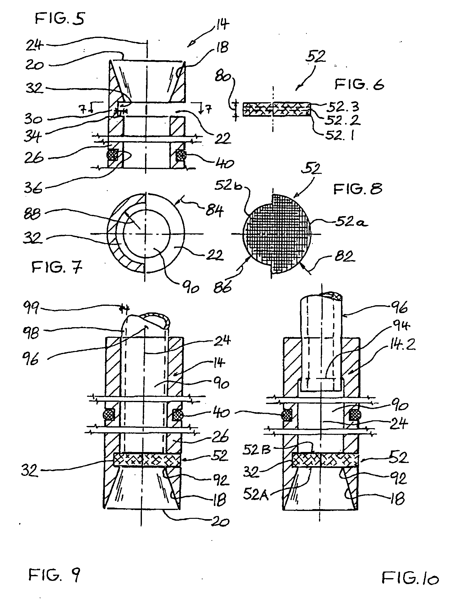
[0017] Since it can be pushed into the inner groove of the piston from the inside, the filter, as seen in plan view, has, at least in one sub-region, a partially circular surface of which the radius is no greater than the internal radius of the piston in the region of the groove base. The filter may have a circular surface overall as seen in plan view. In this case, rather than terminating flush with the outside of the piston in the region of the slot, it is seated in a sunken manner therein in the region of the slot. It is also possible for the filter to terminate flush with the outside of the piston or even to project some way out of the outer clearance profile of the piston. The projecting region of the filter may then assist the (partial) sealing of the gap between the hollow-cylindrical piston and the circular-cylindrical bore in which the piston is seated. At least in this case, the filter, as seen in plan view, is made up of at least two partially circular surfaces of which the radii are of different magnitudes such that the filter can be pushed into the inner groove of the piston—as before—by way of its smaller partially circular surface.
[0018] In order to ensure that the filter is reliably pushed right into the slot, it is advantageous for the radius of the partially circular surface of the filter which is pushed into the inner groove to be selected to be equal to the internal radius of the groove base. This is because the precise fit of the filter in the piston can then be easily established; the filter has been pushed all the way into the slot only when it strikes against the groove base.
[0025] In order to prevent pulverulent bulk material from penetrating into the filter from the outside through the piston-enclosing annular gap, it is recommended for the radially outer surface of the filter to be designed to be impermeable to the bulk material, in particular air-impermeable. This impermeability can be achieved by a corresponding coating of the filter. Furthermore, it is also possible, this being additionally illustrated in an exemplary embodiment, for a sealing element which is impermeable to the bulk material, for example a sealing element in the form of a ring section, to be introduced into the transverse slot of the piston in addition to the filter. This ring section is present in the cross-sectional region of the piston wall and does not reduce the size of the through-passage opening of the piston and thus the effective filter surfaces of the filter on both sides. Such a sealing element can effectively prevent bulk material from penetrating laterally and radially into the filter medium.

Problems solved by technology

This impairs the metering accuracy of this dispensing apparatus.
Moreover, the filter, which is designed as a hollow body, is difficult to access and thus involves very high outlay in order to be removed and installed, for example, for cleaning purposes.
This problem is also present in the case of the metering roller which is known from DE 31 15 589 A1.
It is not possible to control, for all practical purposes, whether, and how much, pulverulent bulk material is sucked into the annular perforated-wall regions and blown out again, with the result that impairment to the precision of the respective dispensing quantities is unavoidable.
It is thus not possible for the bulk material sucked into the filter to be subjected uniformly to the action of air over the entire filter surface, and thus to be blown uniformly out of the filter chamber; this is because a central base region located opposite the rod is subjected in an undefined manner to the action of air.
This known filter is relatively costly to remove and clean.
The end surface of this tube, in turn, results in the useable, axially opposite filter surfaces being of different sizes, which, in turn, results in the abovementioned dispensing inaccuracy.
Although the filter is releasable and thus removable, the large number of parts which are to be assembled results in the assembly outlay being very high.

Method used


Image

  • Filter piston apparatus for dispensing pulverulent bulk material
  • Filter piston apparatus for dispensing pulverulent bulk material
  • Filter piston apparatus for dispensing pulverulent bulk material

Examples


Embodiment Construction

[0011] Taking this prior art as the departure point, the object of the invention is to specify a filter piston apparatus for dispensing pulverulent bulk material which allows, as far as possible, constant quantities of pulverulent bulk material to be dispensed. Nevertheless, this filter piston apparatus is to be capable of being operated as cost-effectively as possible.

[0012] This invention is achieved by the features of claim 1. Expedient developments of the invention form the subject matter of further claims which follow claim 1.

[0013] The filter piston apparatus according to the invention has a comparatively small number of components, which are of straightforward configuration. By virtue of the piston being plugged to different extents into the circular-cylindrical bore provided for it, the size of the metering chamber can be variably adjusted in a very straightforward manner. It is also possible for the filter to be pushed into the hollow-cylindrical piston from the side, and...


PUM

PropertyMeasurementUnit
circumferential angleaaaaaaaaaa
grain sizeaaaaaaaaaa
grain diameteraaaaaaaaaa

Abstract

A filter piston apparatus (10) for dispensing respectively predetermined volumes of pulverulent bulk material (50) has a metering chamber (13) which accomodates in each case a predetermined volume of bulk material (50), which is present at the end of the circular-cylindrical bore (12) and which has its base formed by the filter (52) of the piston (14). It is possible for the metering chamber (13) to be attached to a positive-pressure or negative-pressure gas source through a filter (52), which is permeable to gas but impermeable to the bulk material. The wall of the piston (14) has a transverse slot (22) and an inner groove (32) located radially opposite the transverse slot (22), such that the filter (52) can be pushed into the slot (22) from the outside and, in its state in which it is seated in the piston (14), can be secured on both sides in the axial direction (24) of the piston (14) along its periphery.

Description

TECHNICAL FIELD [0001] The invention relates to a filter piston apparatus for dispensing pulverulent bulk material. The respective dispensing quantities have a predetermined, as far as possible, constant volume. By means of the filter piston apparatus, the volume of pulverulent bulk material which is to be dispensed in each case is introduced into a metering chamber and retained there in a force-fitting manner as the filter piston apparatus is transported to a container which is to be filled in each case. The pulverulent bulk material which is present in the metering chamber is then emptied, by the filter piston apparatus, into the correspondingly available container. For the purpose of filling the metering chamber, pulverulent bulk material is sucked into the metering chamber, and it is blown out of the metering chamber when the latter is emptied. For this purpose, a negative air pressure or positive air pressure may be generated in the interior of the metering chamber. [0002] Such...

Claims


Application Information

Patent Timeline
Patent Type & Authority Applications(United States)
IPC IPC(8): B65B1/16B65B1/36B65B1/38
CPCB65B1/16B65B1/385B65B1/366Y10T137/86871
Inventor ZILL, TOBIASREISER, MANFRED
Owner HARRO HOFLIGER VERPACKUNGSMASCHEN
Learn More