Motor and motor manufacturing apparatus
a manufacturing apparatus and motor technology, applied in the manufacture of stator/rotor bodies, synchronous machines with stationary armatures and rotating magnets, dynamo-electric components, etc., can solve the problems of reducing the cogging torque component caused by magnetic anisotropy and the inability to reduce the cogging torque by such methods, and achieve the effect of reducing the cogging torqu
- Summary
- Abstract
- Description
- Claims
- Application Information
AI Technical Summary
Benefits of technology
Problems solved by technology
Method used
Image
Examples
first embodiment
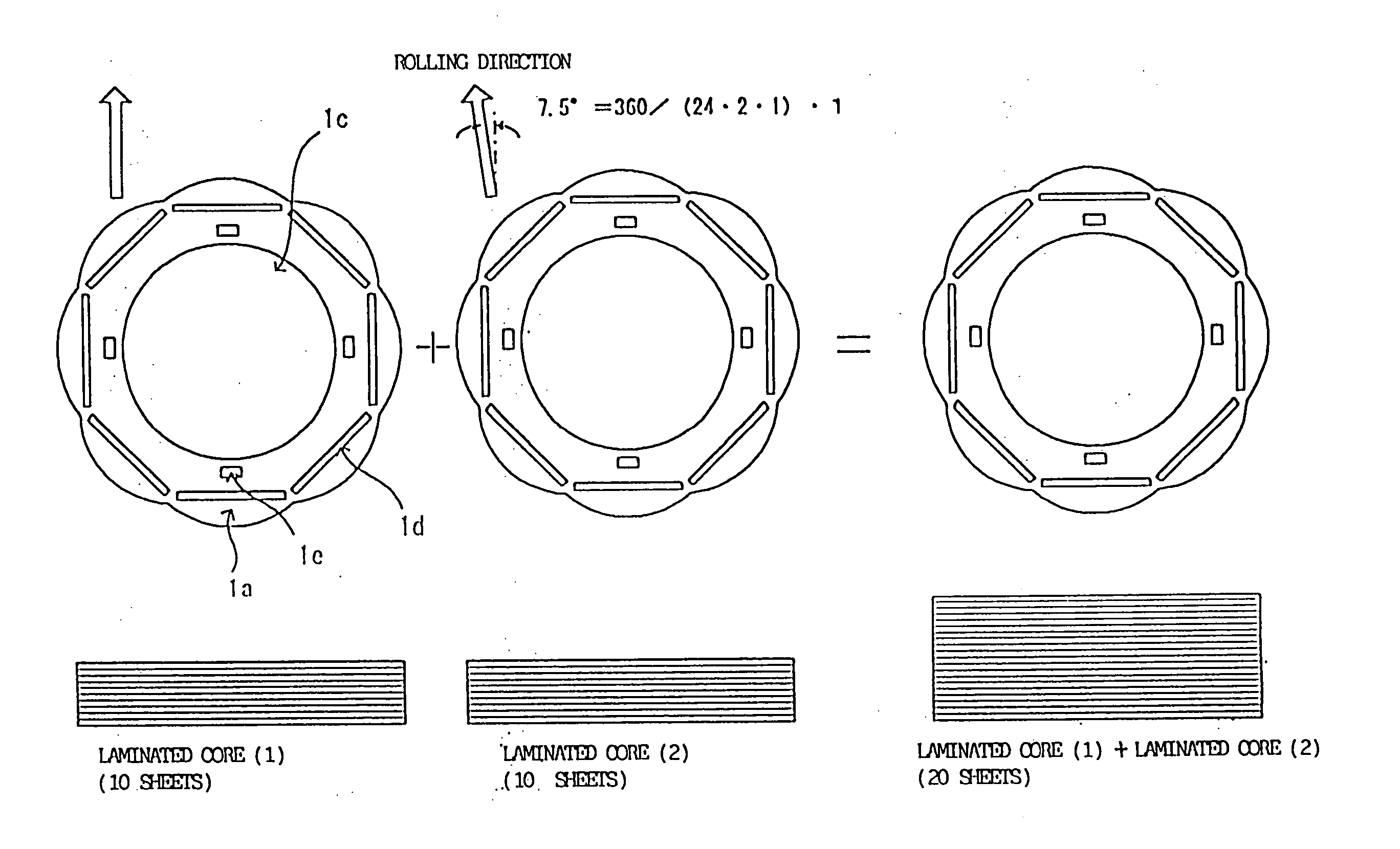
[0130] In fabricating the cores with different rolling directions, flat rolled magnetic steel sheet and strip which is a core workpiece is punched out by turning through the prescribed angle with respect to the punching die. The motor manufacturing apparatus turns the core workpiece with a feed mechanism located inside the die and forms the cores in which the rolling directions are shifted by the prescribed angle with the punching die.
[0131]FIGS. 16A and 16B illustrate the first embodiment of fabricating the cores. Referring to FIG. 16A, a core is punched out with a punching die after the rolling direction of the core workpiece has been matched with the prescribed direction (prescribed angle) with respect to the punching die. In FIG. 16A, the reference symbol 5A in figure (a2) represents a punching die. After the core 1a has been punched out with the punching die 5A, the core workpiece is turned through the prescribed angle with the feed mechanism located in the die, as shown in FIG...
second embodiment
[0132] In fabricating the cores with different rolling direction, punching is conducted by turning the punching die through the prescribed angle with respect to the rolling direction of the flat rolled magnetic steel sheets and strip which is the core workpiece. In the motor manufacturing apparatus, the punching die is turned by the feed mechanism located in the die and the cores are formed with a rolling direction shifted by the prescribed angle by the punching die.
[0133]FIGS. 17A and 17B illustrate the second embodiment of fabricating the cores. Referring to FIG. 17A, a core is punched out with a punching die after the punching die has been matched with the prescribed direction (prescribed angle) with respect to the rolling direction of the core workpiece. In FIG. 17A, the reference symbol 5A in figure (a2) represents a punching die. After the core 1a has been punched out with the punching die 5A, the punching die is turned through the prescribed angle with the feed mechanism loca...
third embodiment
[0134] In fabricating the cores with different rolling directions, a plurality of punching dies are prepared, those dies having different angles with respect to the rolling direction of the flat rolled magnetic steel sheets and strip which is the core workpiece, and the cores with different angles are punched out with those dies. The motor manufacturing apparatus comprises a plurality of punching dies with different angles with respect to the rolled steel.
[0135]FIGS. 18A and 18B illustrate the third embodiment of fabricating the cores. Referring to FIG. 18A, a core is punched out with a punching die after the punching die has been matched with the prescribed direction (prescribed angle) with respect to the rolling direction of the core workpiece. In FIGS. 18A and 18B, the reference symbols 5A and 5B in figures (a2) and (b2) represent punching dies. The punching dies 5A and 5B punch out respective cores 1a and form cores 1a which are shifted by the prescribed angle with respect to th...
PUM
| Property | Measurement | Unit |
|---|---|---|
| Angle | aaaaa | aaaaa |
| Angle | aaaaa | aaaaa |
| Shape | aaaaa | aaaaa |
Abstract
Description
Claims
Application Information
 - R&D
- Intellectual Property
- Life Sciences
- Materials
- Tech Scout
- Unparalleled Data Quality
- Higher Quality Content
- 60% Fewer Hallucinations
Browse by: Latest US Patents, China's latest patents, Technical Efficacy Thesaurus, Application Domain, Technology Topic, Popular Technical Reports.
© 2025 PatSnap. All rights reserved.Legal|Privacy policy|Modern Slavery Act Transparency Statement|Sitemap|About US| Contact US: help@patsnap.com


