Method for driving light emitting diode

a technology of light-emitting diodes and motors, which is applied in the direction of electric variable regulation, process and machine control, instruments, etc., can solve the problems of excess power loss and low efficiency of charge pumping in the prior art, and achieve the effect of excess power loss and low charge pumping efficiency

Active Publication Date: 2005-02-03
ANALOG INTEGRATIONS CORP
View PDF5 Cites 20 Cited by
  • Summary
  • Abstract
  • Description
  • Claims
  • Application Information

AI Technical Summary

Benefits of technology

[0007] It is an aspect of the present invention to provide a method for driving a light emitting diode with a current mirror. When the input voltage of a current mirror is increased and the voltage difference between the input and the output of the current mirror is fixed, the low efficiency of the charge pumping and the excess power loss in the prior art are overcome.

Problems solved by technology

When the input voltage of a current mirror is increased and the voltage difference between the input and the output of the current mirror is fixed, the low efficiency of the charge pumping and the excess power loss in the prior art are overcome.

Method used


Image

  • Method for driving light emitting diode
  • Method for driving light emitting diode
  • Method for driving light emitting diode

Examples


Embodiment Construction

[0034] The invention is described more specifically with reference to the following embodiments. It is to be noted that the following descriptions of preferred embodiments of this invention are presented herein for the purpose of illustration and description only; it is not intended to be exhaustive or to be limited to the precise form disclosed.

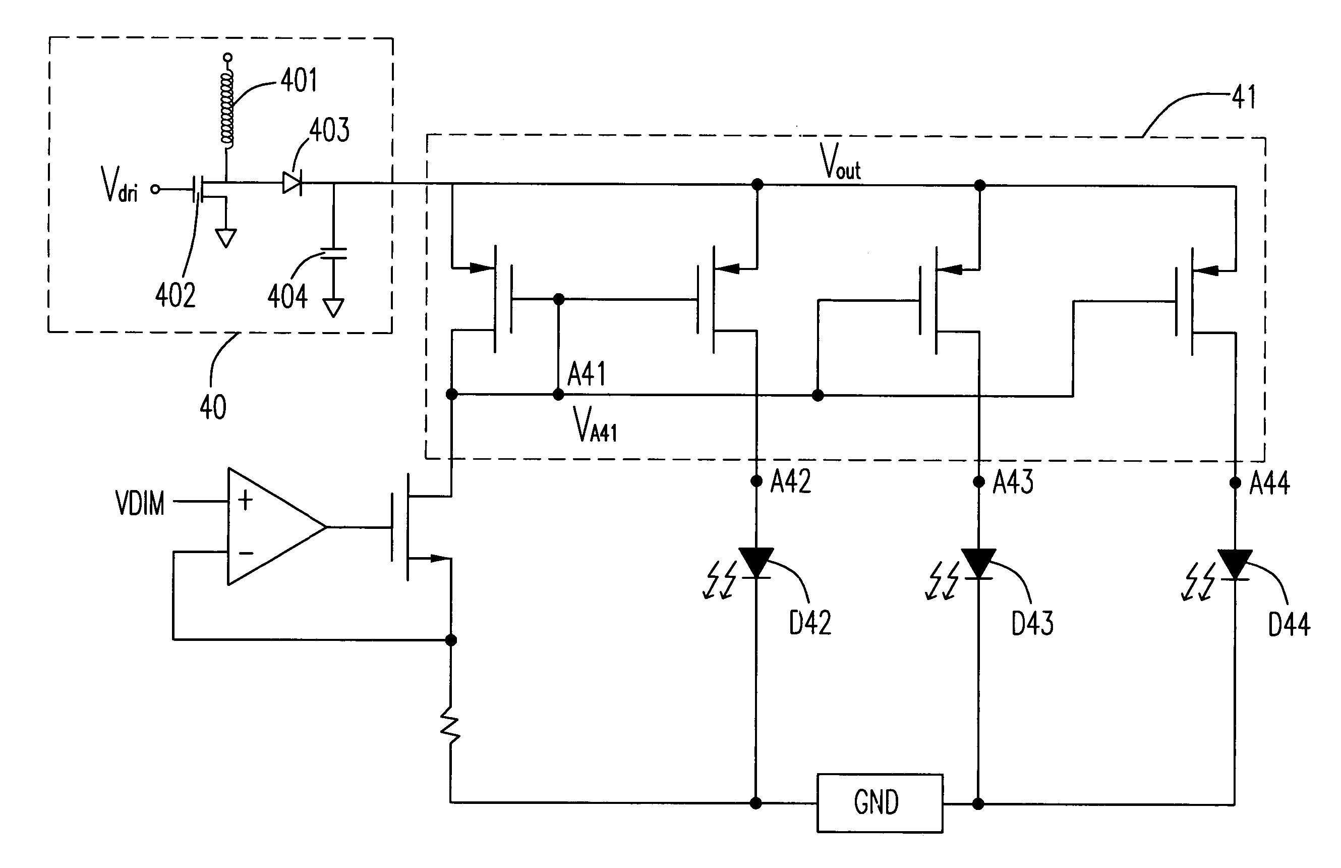
[0035] Please refer to FIG. 4 showing a circuit diagram of a light emitting diode driven by a current mirror according to the preferred embodiment of the present invention. The voltage of the input of a current mirror 41 is increased by an inductive charge pumping circuit 40 for driving a plurality of light emitting diodes (LED) coupled to the current mirror 41. The light emitting diodes are not limited to white light, blue light or any other colors of light emitting diodes. For simplifying the descriptions of the present invention, the current mirror 41 constructed by four metal-oxide-semiconductor transistors and three white light emittin...


PUM


Abstract

A method for driving a light emitting diode coupled to an output of a current mirror is provided. The method includes providing a control terminal voltage of the current mirror as a reference voltage, increasing a voltage of an input of the current mirror and providing an input of the light emitting diode as a voltage feedback point for keeping a constant voltage difference between the input and the output of the current mirror, and driving the light emitting diode by a voltage at the output of the current mirror.

Description

FIELD OF THE INVENTION [0001] This invention relates to a method for driving a light emitting diode, and more particularly to a method for driving a light emitting diode coupled to an output of a current mirror. BACKGROUND OF THE INVENTION [0002] Referring to FIG. 1, it is shown that a charge pump circuit is conventionally used for a current mirror to drive a light emitting diode (LED). Charges are stored and transmitted depending on the one-way transmission of the diode-connected MOS and the capacitance, and therefore a high voltage is formed and output. The conventional charge pump circuit is formed by connecting several pump circuit units 11 in series. Please refer to FIG. 2. Each pump circuit unit 11 is formed by coupling a first capacitor C22, a first transistor N23, a second capacitor C25 and a second transistor N26, wherein the first transistor N23 is connected to the second transistor N26 to form a common drain, then the common drain is connected to one end of the first capa...

Claims


Application Information

Patent Timeline
Patent Type & Authority Applications(United States)
IPC IPC(8): H01S3/08H05B44/00H01L33/00
CPCH05B33/0827H05B33/0815H05B45/46H05B45/37H05B45/397Y02B20/30
Inventor LEE, ALBERT MINRUFENG, WEI WEN
Owner ANALOG INTEGRATIONS CORP
Why Eureka
Try Eureka