
Charger

a charging device and charger technology, applied in the field of chargers, can solve the problems of low charging efficiency of conventional chargers and efficient power transmission, and achieve the effect of low charging efficiency and high charging efficiency

Inactive Publication Date: 2009-07-23
KK TOSHIBA
View PDF10 Cites 9 Cited by
  • Summary
  • Abstract
  • Description
  • Claims
  • Application Information

AI Technical Summary

Benefits of technology

[0007]As described above, conventional chargers have a problem of low charging efficiency. The present invention was made to solve such a problem and its object is to provide a charger realizing highly efficient charging.

Problems solved by technology

The sensor requires to be equipped with a battery since power supplied by radio transmission is not enough for its operation.
Generally, in the radio power transmission, a transmission loss is large and therefore, it is a significant issue how the power is transmitted efficiently to charge the battery.
As described above, conventional chargers have a problem of low charging efficiency.

Method used


Image

  • Charger
  • Charger
  • Charger

Examples


Embodiment Construction

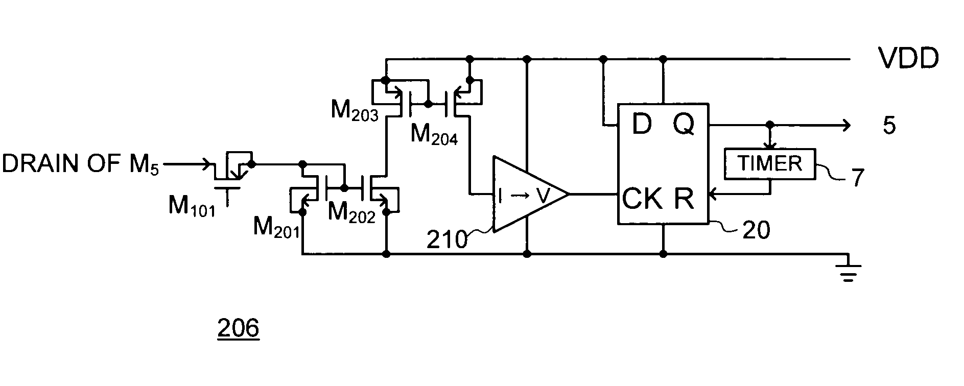
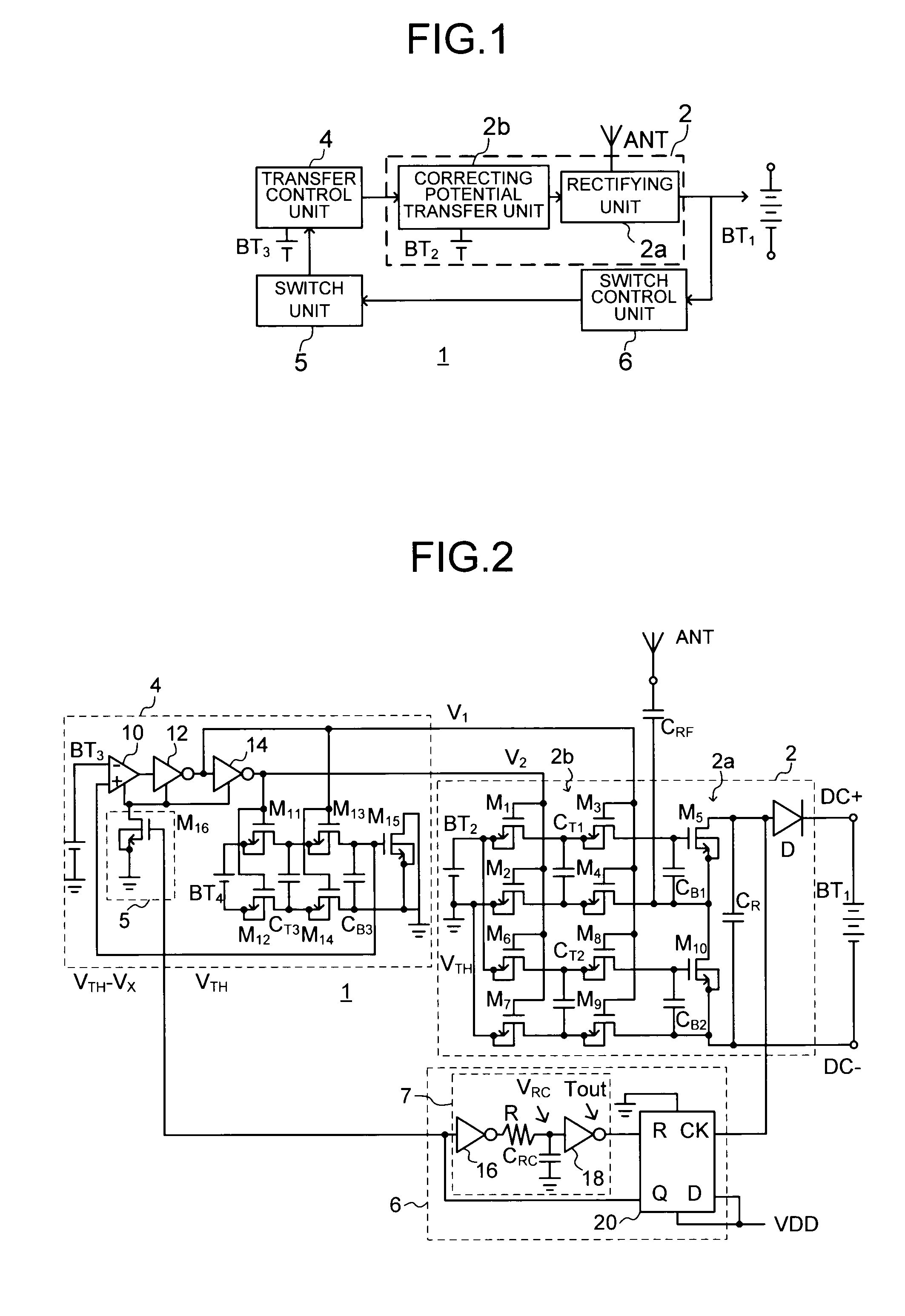
[0017]As result of rectification and detection of a radio wave received by an antenna, a DC current can be obtained. That is, a charger supplying power by radio transmission can be realized if it rectifies a radiowave received from a radiowave sender and supplies the obtained DC current to a chargeable battery.

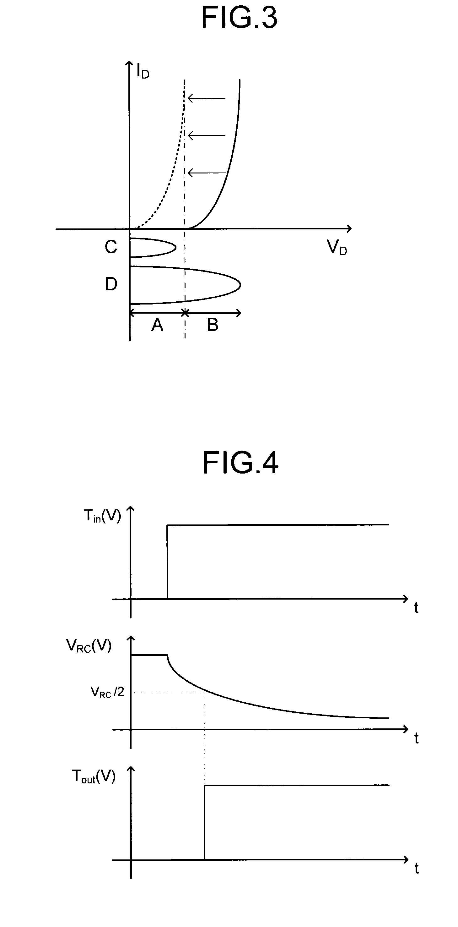
[0018]A diode element (including a semiconductor element such as a transistor used as a diode) used for the rectification has a property that a current does not flow therethrough unless a forward voltage reaches a certain level or higher. Therefore, when the radio wave received by the antenna is weak and thus the forward voltage (output voltage of the element) at the certain level or higher cannot be obtained, a sufficient charging current cannot be obtained, resulting in deteriorated efficiency of the whole charger. In a charger according to an embodiment of the present invention, a voltage applied to the diode element used for the rectification is increased to offset a thres...


PUM


Abstract

A charger includes: a rectifier to rectify a received radio wave to generate a charging current; a potential generator to generate a bias voltage setting an operating point of the rectifier; and a controller to supply the bias voltage generated by the potential generator when an output voltage of the rectifier is equal to or larger than a predetermined value.

Description

CROSS-REFERENCE TO RELATED APPLICATIONS[0001]This application is based upon and claims the benefit of priority from the prior Japanese Patent Application No. 2008-011673, filed on Jan. 22, 2008; the entire contents of which are incorporated herein by reference.BACKGROUND[0002]1. Field of the Invention[0003]The present invention relates to a charger using radio technology, in particular, to a charger with enhanced charging efficiency.[0004]2. Description of the Related Art[0005]In recent years, so-called RF tags have been under active research and development. The RF tag is a non-contact data carrier that electronically reads and updates package information by using radio technology. In recent years, an RF tag which is combined with a sensor and can read information obtained by the sensor has also been developed. The sensor requires to be equipped with a battery since power supplied by radio transmission is not enough for its operation.[0006]The battery mounted in the RF tag is desir...

Claims


Application Information

Patent Timeline
Patent Type & Authority Applications(United States)
IPC IPC(8): H02J7/00
CPCH02J7/022Y02B40/90H02J17/00H02J50/20H02J7/02H02J2207/20Y02B40/00
Inventor OTAKA, SHOJIUMEDA, TOSHIYUKI
Owner KK TOSHIBA
Learn More