Simultaneous transmission of multiple signals through a common shared aperture

a technology of shared aperture and simultaneous transmission, which is applied in the direction of instruments, measurement devices, and using reradiation, etc., can solve the problems of inability to realize the full gain of the antenna on any of the user signals, the platform cannot carry, nor operate properly, and all the desired electronic equipmen

Inactive Publication Date: 2005-02-03
NAVY THE U S A AS REPRESENTED BY THE SECU OF THE
View PDF4 Cites 98 Cited by
  • Summary
  • Abstract
  • Description
  • Claims
  • Application Information

AI Technical Summary

Benefits of technology

In this invention, a diverse waveform is formed from multiple signals and transmitted through a common array aperture. The invention provides a new technique that provides a transformation that shapes and combines multiple signals prior to power amplification and an inverse transformation that converts the transformed phase-modulated (PM) signals back into a high-power, low-distortion, amplitude-varying waveform. This technique allows simultaneous transmission of multiple signals through every saturated power amplifier in the array antenna without serious intermodulations and spectral distortion. To implement this technique in wideband operations, innovative amplitude-to-phase-modulation (AM-PM) processes in associated with the inverse transformations capable of transmitting combined waveforms are devised.

Problems solved by technology

In many instances, the platforms can no longer properly carry, nor operate, all the desired electronic equipment.
If two signals are simultaneously present at the power amplifier input, the resulting output signal will generally be highly distorted and contain extremely high intermodulations, thus causing serious problems for the nearby receive antenna.
Alternately, if the amplifier is operated in a linear mode, significant power and efficiency are lost.
As a result, the full gain of the antenna cannot be realized on any of the user signals that are required for simultaneous transmission.
However, sharply confining the spectra requires signal shaping2 in the time domain that causes amplitude modulation of the waveforms.

Method used


Image

  • Simultaneous transmission of multiple signals through a common shared aperture
  • Simultaneous transmission of multiple signals through a common shared aperture
  • Simultaneous transmission of multiple signals through a common shared aperture

Examples


Embodiment Construction

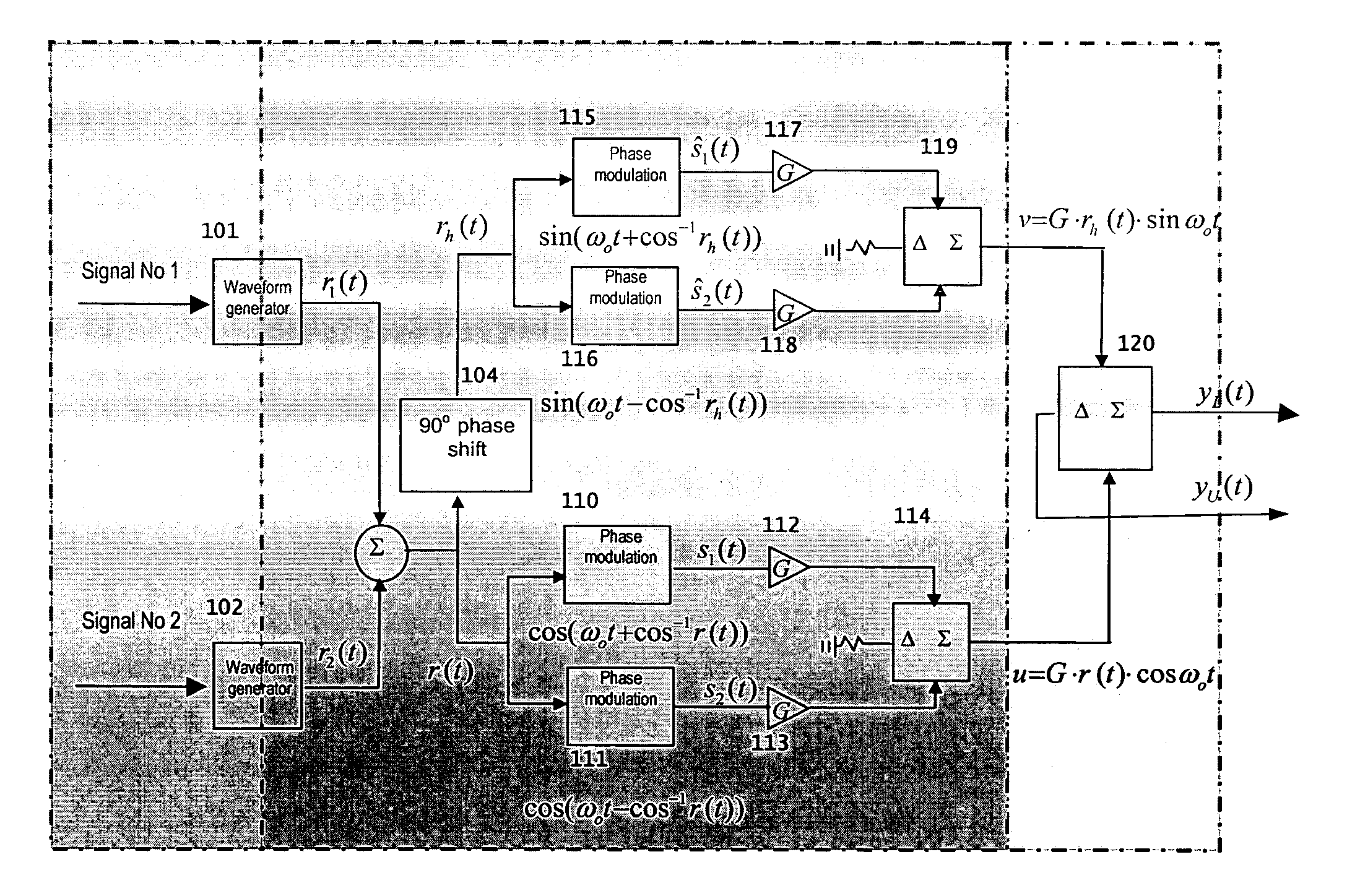
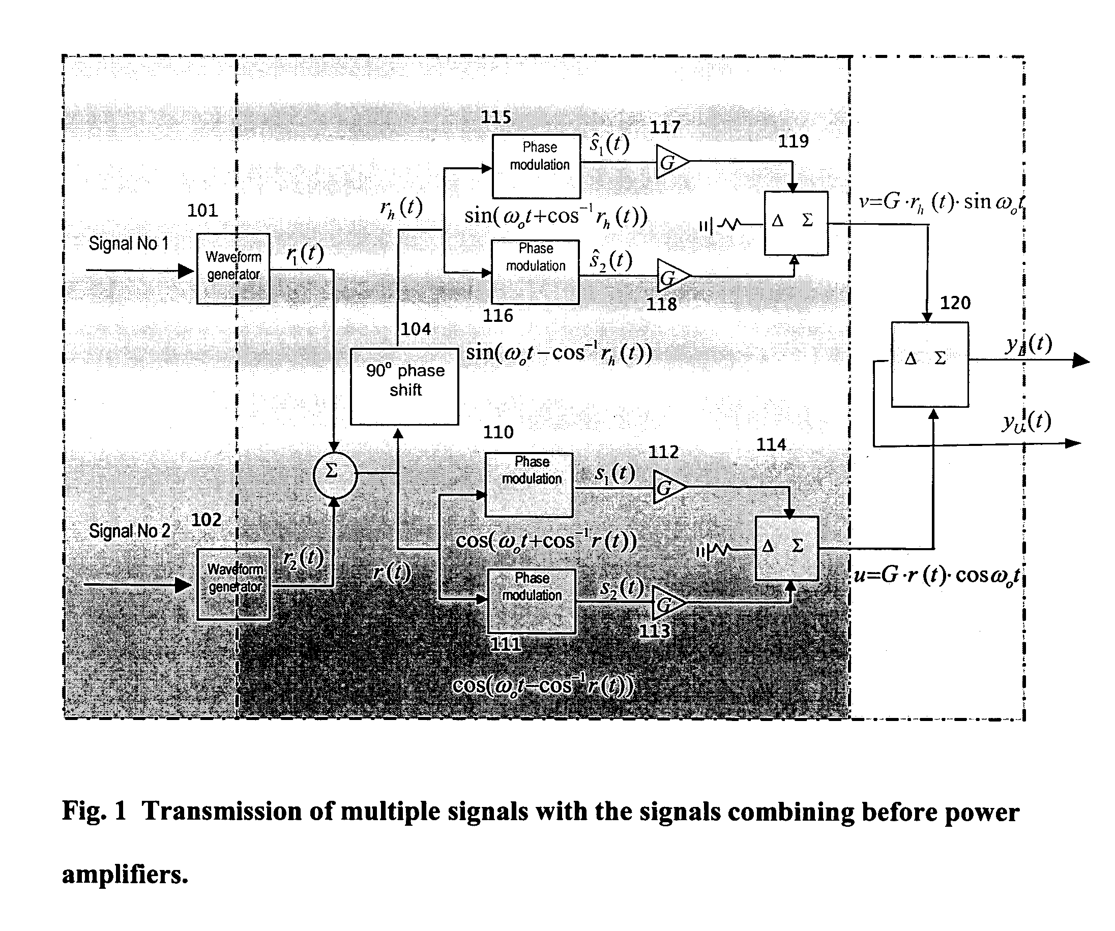
The detailed description of the invention closely follows the block diagrams and figures shown in FIGS. 1 through 12. FIG. 1 is the overall block diagram describing the new technique in transmitting a high power diverse waveform without serious intermodulations and spectral distortion. FIGS. 2 through 4, which are sub-blocks of FIG. 1, detail the practical implementation. FIGS. 5 through 11 are the signal outputs, appearing in time or frequency domains, for some critical blocks shown in FIG. 3

Transmission of Multiple Signals With the Signals Combining Before Power Amplifiers—FIG. 1

FIG. 1 is the overall block diagram describing the new technique in transmitting a high power diverse waveform without serious intermodulations and spectral distortion.

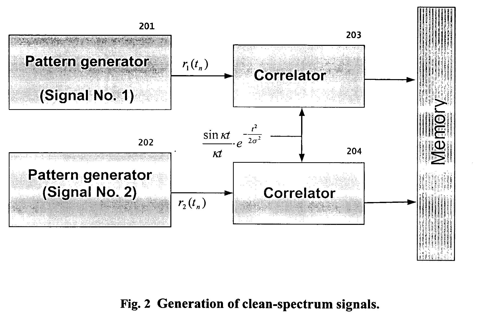
In Blks 101 and 102, clean-spectrum signals r1(t) and r2(t) are generated through the waveform generators in that desired waveforms are generated and passed through the correlators and Digital to Analog converters (DAC). These signals r1...


PUM


Abstract

In phased array antennas, multiple signals that perform different functions, such as radar, electronic warfare (EW) and telecommunications, can each be simultaneously transmitted only through a different sub-aperture of the array. For maximum power and efficiency, the power amplifiers operate on one signal at a time. This patent provides the technique of forming a common waveform from multiple signals for transmission through a common aperture. To practically implement this technique in wideband operations, processes performing the required waveform-shaping and amplitude-to-phase-modulation are devised that can transmit the high-power diverse waveforms without serious intermodulations and spectral distortion through every element of the array.

Description

BACKGROUND OF THE INVENTION 1. Field of the Invention In phased array antennas, multiple signals (such as radar, electronic warfare (EW), and communications waveforms) can each be simultaneously transmitted only through a different sub-aperture of the array. For maximum power and efficiency, the power amplifiers operate on one signal at a time. This invention is to form multiple signals as a common waveform and transmit them through a common shared array aperture. The user signals are thus transmitted simultaneously and independently with full antenna gain in any direction. 2. Description of the Related Prior Art The number of electronic equipments and associated antennas carried on military platforms continues to grow rapidly. In many instances, the platforms can no longer properly carry, nor operate, all the desired electronic equipment. To alleviate this problem, a significant initiative called the Advanced Multi-Function Radio-Frequency Aperture Concept (AMRFC)1 was undertak...

Claims


Application Information

Patent Timeline
Patent Type & Authority Applications(United States)
IPC IPC(8): G01S7/35G01S13/02
CPCG01S7/35G01S2013/0272G01S2013/0245
Inventor CANTRELL, BENLIN, CHING-TAI
Owner NAVY THE U S A AS REPRESENTED BY THE SECU OF THE
Why Eureka
Try Eureka