
Container illumination

a technology for lighting containers and containers, applied in the field of new consumer lighting assemblies, can solve the problems of limited illuminating container assemblies, known illuminating devices are limited to specific container sizes or configurations,

Inactive Publication Date: 2005-02-03
JOHNSON RICHARD
View PDF11 Cites 74 Cited by
  • Summary
  • Abstract
  • Description
  • Claims
  • Application Information

AI Technical Summary

Benefits of technology

[0013] In another embodiment a squeezable tube is designed with a pocket, cavity or pouch to allow the temporary or permanent insertion of a lighting source. The pocket, cavity or pouch may also be fitted with a means to permanently or temporarily seal the lighting source inside the pocket, cavity or pouch, such as a zip-lock, zipper, button, Velcro or other sealing means. After insertion and circuit activation, the lighting source will illuminate the contents of the squeezable tube and also illuminate the contents as they are squeezed out of the tube, thus creating an entertaining illumination effect. It is anticipated that this embodiment would be well-suited toward tube dispensed frozen confections, toothpaste, hair-care products, candy confections, creams, gels, and other suitably viscous tube dispensed consumer products. It is anticipated that more solid or firm containers such as rigid plastic, glass or aluminum containers would be fit with a cavity designed to sustain and hold an inserted illumination source snugly in place. These types of containers could provide illumination for liquids, shampoos, auto products, food products and other consumable products dispensed from cans or bottles.
[0014] In another embodiment a self sealing container piercing light emitting tube or rod is forcibly inserted into an aluminum or plastic container. This particular embodiment is designed to illuminate the interior and contents of an opaque container. One version of this embodiment calls for the shaking of a carbonated beverage can, and upon insertion of the illumination tube, the pressurized carbonated beverage spews out forcibly through the tube with said liquid glowing and illuminated from the light beam in the tube creating and exploding illuminated liquid effect from the can. It is anticipated that the self-sealing aspect of the piercing tube or rod includes a plug assembly to suitably seal the contents of the container. One of the main more practical utilities of this embodiment is the capability of viewing the remaining contents of a sealed opaque container.
[0017] In another embodiment, containers are molded with form fitted indentations suitable to place an LED light, batteries, circuit board and pushbutton. The label is then placed over the inserted parts fitting flush over the container with limited protrusions or bumps from under the label. This particular embodiment requires a custom molded part, but would provide the mass markets with a consistent performing and smooth fitting illumination label means.
[0018] In another embodiment an illumination clip, clips onto the mouth of a bottle, cup or can. The clip can be formed to enhance the pourability of the container, thus reducing spills or drips when poured. This design allows users to illuminate opaque containers such as cans or detergent containers. The combination of a clip on container illumination device with an easy-flow transitional spout feature, creates an added an unexpected utility.

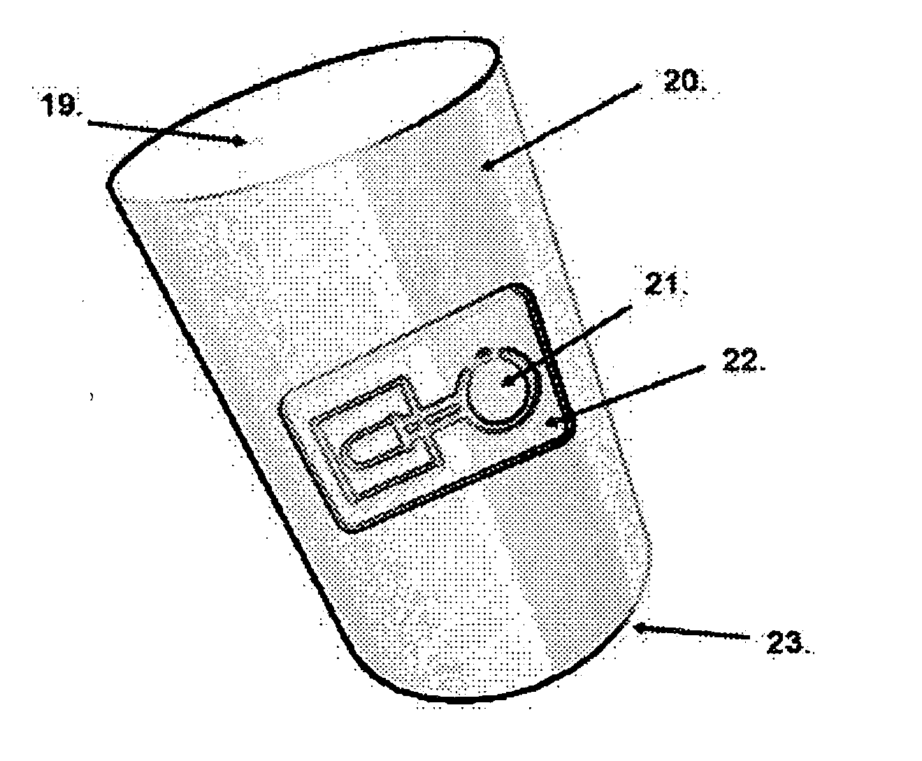
Problems solved by technology

Known illuminating container assemblies are limited to exterior holding devices, primarily related to beverage holders and the like.
Unfortunately, known illuminating devices are limited to specific container sizes or configurations.

Method used


Image

  • Container illumination
  • Container illumination
  • Container illumination

Examples


Embodiment Construction

[0030] While this invention is susceptible of embodiment in many different forms, there is shown in the drawings, and will herein be described in detail, exemplary embodiments, with the understanding that the present disclosure is to be considered as illustrative of the principles of the invention and not intended to limit the invention to the exemplary embodiments shown and described.

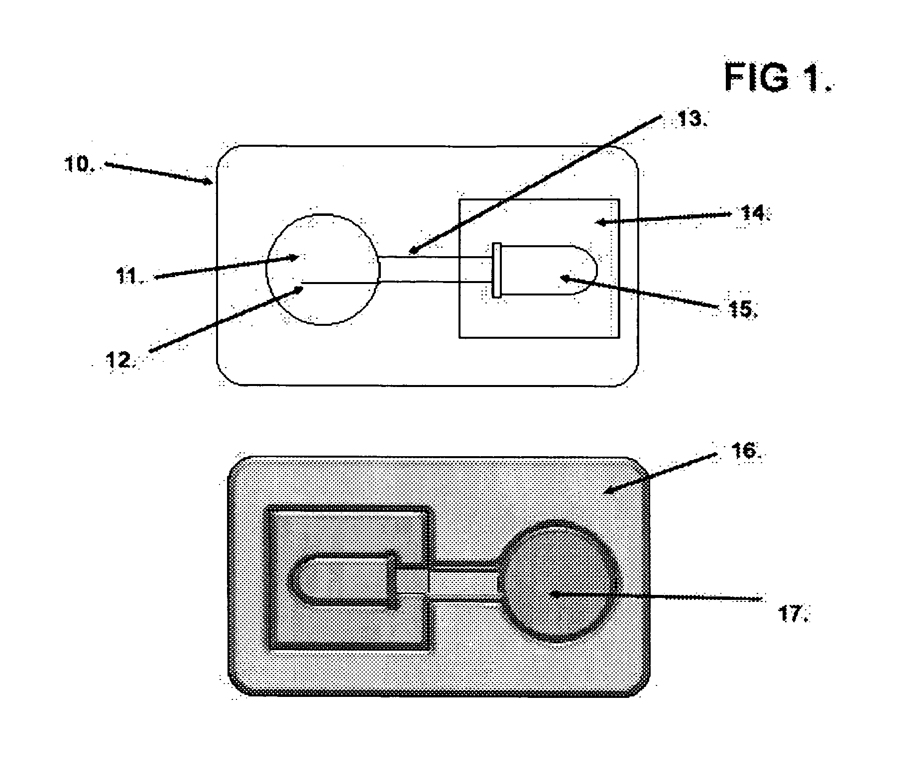
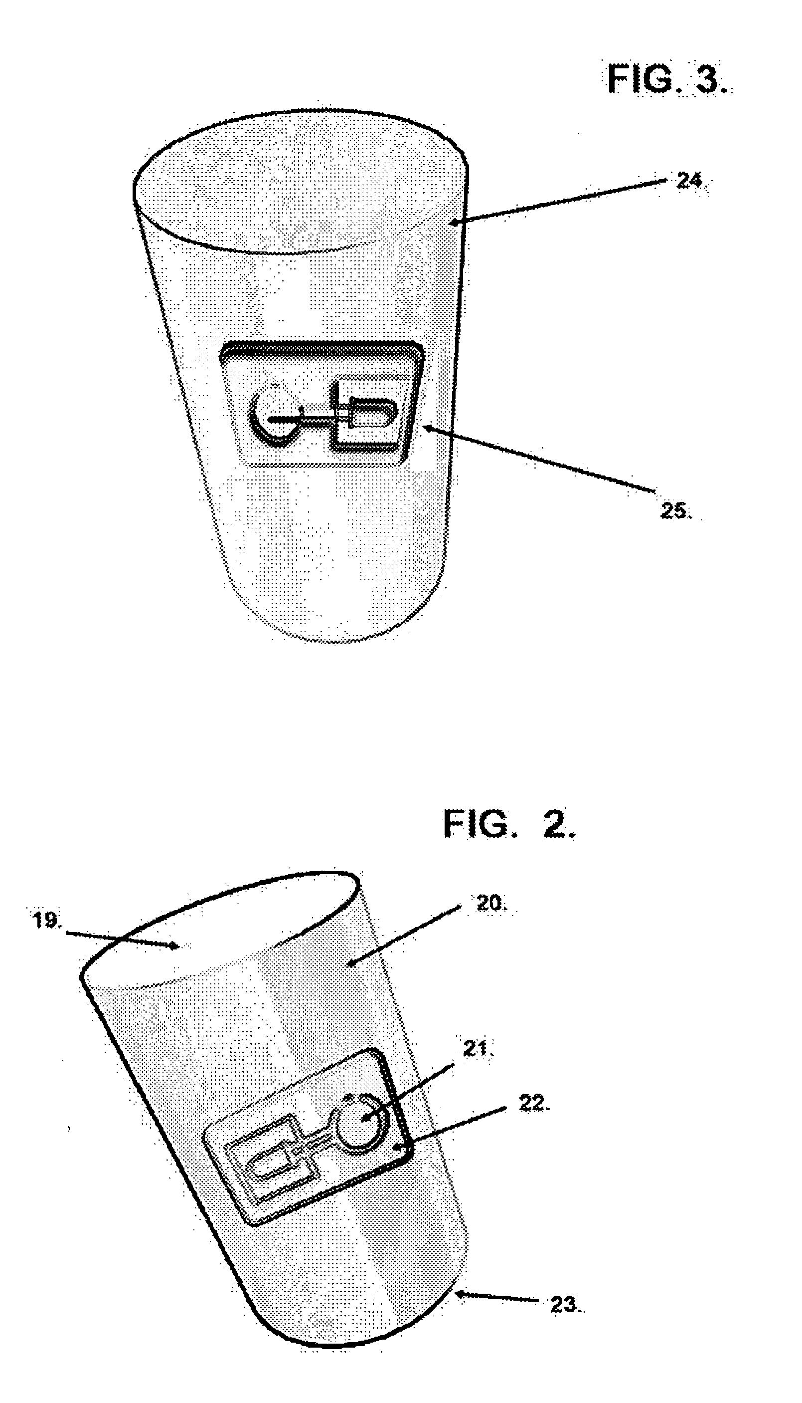
[0031]FIG. 1 represents a schematic of an illuminating flexible sheet, which can be provided in the form of an adhesive sticker or label. The label or sticker, 10 can be made of a suitable material such as paper, plastic or metal foil and may optionally contain preformed foam indentations to ideally fit the size and shape of the light assembly components. The components of the light source assembly are systematically stuck to, or into the label perforations as either preformed or by an adhesive. The sticker or label is applied to a container and may be activated by a battery and switch source 11, conn...


PUM


Abstract

A container illumination assembly for use with a standard includes a selectively actuatable light source. A connection mechanism is adapted and constructed to secure the light source to the standard container. With the light source secured to the standard container with the connection mechanism, the contents of the standard container are selectively illuminated by the light source when the light source is actuated.

Description

FIELD OF THE INVENTION [0001] The present invention relates generally to novelty consumer lighting assemblies, specifically the illumination of handheld containers. BACKGROUND OF THE INVENTION [0002] There are few things that fascinate and entertain like unexpected light up objects. Since the invention of the incandescent light, millions of people have been entertained with Christmas tree lights, lights up toys, and hundreds of other consumer novelty light up devices. There have been thousands of variations regarding the design and implementation of novelty light up devices. Recently with the trend of decreasing LED lighting prices throughout the world, producers are marketing numerous novelty products for increased entertainment, utility and enjoyment in dark areas. [0003] Known illuminating container assemblies are limited to exterior holding devices, primarily related to beverage holders and the like. For example, U.S. Pat. No. 6,352,352 Schletterer, et al. is directed to a lumin...

Claims


Application Information

Patent Timeline
IPC IPC(8): A45D34/00A47G19/22B65D25/20F21V33/00G09F23/08
CPCA45D2034/002A47G19/2227A47G2019/2238G09F23/08B65D2203/02B65D2203/12F21V33/0028B65D25/20
Inventor JOHNSON, RICHARD
Owner JOHNSON RICHARD
Learn More