
Coated article with high visible transmission and low emissivity

a technology of visible transmission and low emissivity, applied in the direction of vacuum evaporation coating, natural mineral layered products, transportation and packaging, etc., can solve the problem that the ig unit is still not able to achieve a visible transmission of at least 70%, and achieve the effect of high visible transmission

Inactive Publication Date: 2005-02-03
GUARDIAN GLASS LLC
View PDF29 Cites 26 Cited by
  • Summary
  • Abstract
  • Description
  • Claims
  • Application Information

AI Technical Summary

Benefits of technology

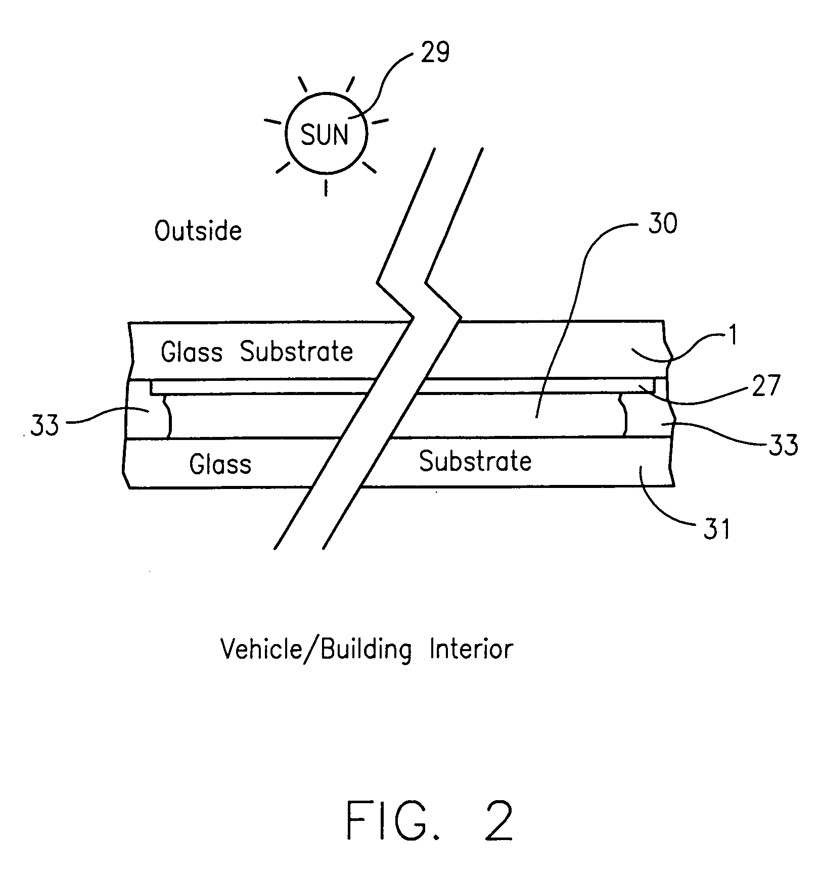
[0004] An object of this invention is to provide a coated article that can be used in applications such as insulating glass (IG) units, so that resulting IG units can achieve high visible transmission of at least 70% (e.g., when using clear glass substrates from 1.0 to 3.5 mm thick), combined with at least one of: (a) SHGC no greater than about 0.45, more preferably no greater than about 0.40; (b) SC no greater than about 0.49, more preferably no greater than about 0.46; (c) chemical and / or mechanical durability; (d) neutral transmissive color such that transmissive a* is from −5.0 to 0 (more preferably from −3.5 to −1.5), and transmissive b* is from −2.0 to 4.0 (more preferably from 1 to 3.0); and (e) neutral reflective color from the exterior of the IG unit (i.e., Rg / Rout) such that reflective a* is from −3.0 to 2.0 (more preferably from −2.0 to 0.5), and reflective b* is from −5.0 to 1.0 (more preferably from −4.0 to −1.0).

Problems solved by technology

Even using these thin clear glass sheets (2.3 mm thick), the IG unit was still not able to achieve a visible transmission of at least 70%; this is unfortunate in certain non-limiting situations.

Method used


Image

  • Coated article with high visible transmission and low emissivity
  • Coated article with high visible transmission and low emissivity
  • Coated article with high visible transmission and low emissivity

Examples


examples 1-2

[0054] The following example coated articles (Examples 1 and 2) were made in accordance with the FIG. 3 embodiment above (i.e., layer 23 was not present in the coating 27). In Example 1, the FIG. 3 coating or layer system 27 was sputtered onto a 3 mm thick clear soda lime silica glass substrate, using a known Leybold sputter coater (27 cathode system) at a line speed of 2.5 meters per minute. The sputter coater was set up / run as set forth below in Table 5 for Examples 1-2. Power (P) was measured in kW, current (I) in amps, and pressure (Press.) in mbar. The gas flow for Ar gas was measured in sccm, and included Ar gas flow from tuning gas segments. Thus, for example, for cathode 1, there was 350 sccm of main Ar gas flow, and all three tuning gas segments were each adjusted to output 50 sccm each of Ar gas for that cathode, which adds up to 500 sccm of Ar gas flow for cathode 1. For cathodes 1 and 2, oxygen gas flow was controlled and determined by setting all three set points (SP) f...

example 3

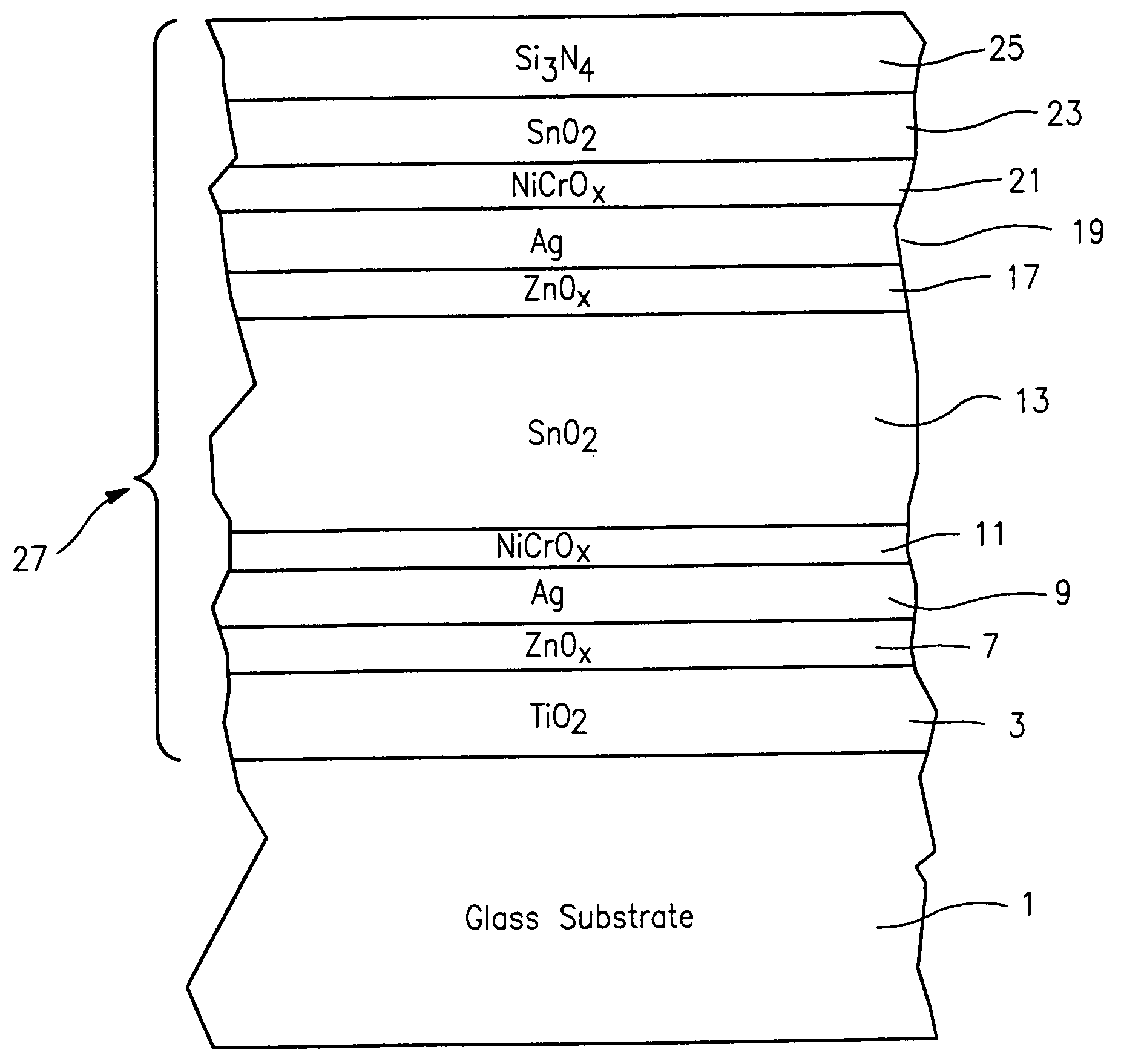
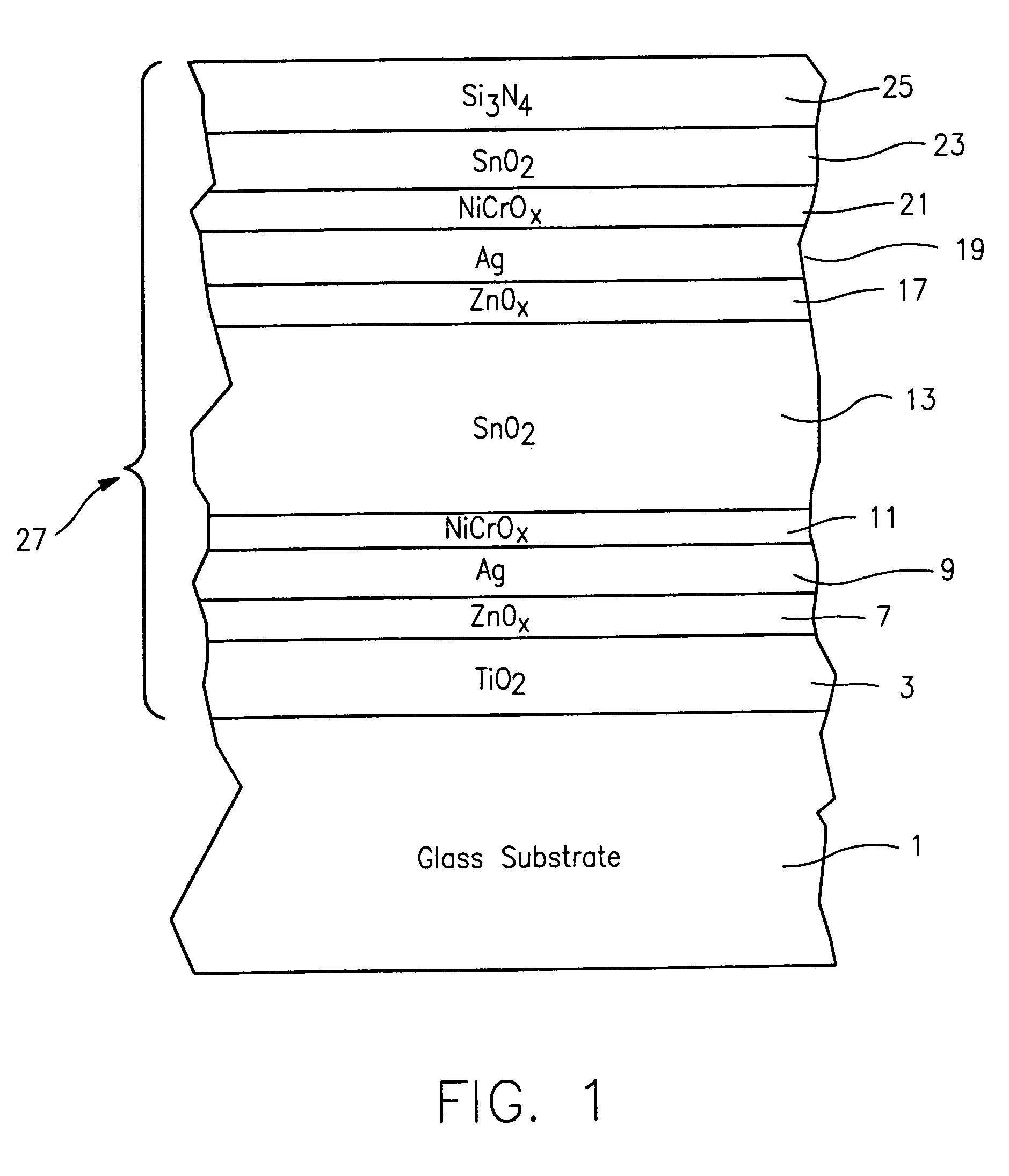
[0057] Example 3 is a theoretical example, and its characteristics are set forth below, including both coater set-up data and solar characteristic data. While Examples 1-2 dealt with the FIG. 2-3 embodiment, Example 3 relates to the FIG. 1-2 embodiment. Note that cathode #23 is to be used in the sputter coater to form tin oxide layer 23 as shown in FIG. 1.

TABLE 8Example Coater Set-up (Example 3)CathodeTargetVolts (V)P (kW)Ar (sccm)O2 (sccm)N2 (sccm)Press. (mbar)I (amp)#1Ti70475500SP752.73 × 10−390#6Ti65775500SP754.87 × 10−389#7ZnAl6002235053004.83 × 10−345#9Ag4385.5150002.35 × 10−311.8#10NiCr48892508001.43 × 10−318.7#12Sn44016300530755.21 × 10−334#13Sn47621300965755.28 × 10−350#14Sn42321125470751.07 × 10−250#15Sn43422.5125470751.07 × 10−250#16Sn42522125470754.72 × 10−355#18ZnAl3732235057004.71 × 10−372#20Ag3927.3250002.00 × 10−318.8#21NiCr49582507501.99 × 10−316.5#23Sn38724125500902.78 × 10−360#25Si4863535006756.04 × 10−372#26Si44435350012006.04 × 10−379

[0058] Following the sputte...


PUM

PropertyMeasurementUnit
sheet resistanceaaaaaaaaaa
shading coefficientaaaaaaaaaa
SC=SHGCaaaaaaaaaa

Abstract

A coated article that can be used in applications such as insulating glass (IG) units, so that resulting IG units can achieve high visible transmission of at least 70% (e.g., when using clear glass substrates from 1.0 to 3.5 mm thick), combined with at least one of: (a) SHGC no greater than about 0.45, more preferably no greater than about 0.40; (b) SC no greater than about 0.49, more preferably no greater than about 0.46; (c) chemical and / or mechanical durability; (d) neutral transmissive color such that transmissive a* is from −5.0 to 0 (more preferably from −3.5 to −1.5), and transmissive b* is from −2.0 to 4.0 (more preferably from 1.0 to 3.0); and (e) neutral reflective color from the exterior of the IG unit (i.e., Rg / Rout) such that reflective a* is from −3.0 to 2.0 (more preferably from −2.0 to 0.5), and reflective b* is from −5.0 to 1.0 (more preferably from −4.0 to −1.0). In certain example non-limiting embodiments, coated articles herein comprise: substrate / TiOx / ZnOx / Ag / NiCrOx / SnOx / ZnOx / Ag / NiCrOx / SnOx / SixNy.

Description

[0001] This invention relates to a coated article, and a method of making the same. In particular, this invention relates to a coated article having high visible transmission (e.g., absent tempering, heat bending, or other significant heat treatment), neutral color (transmissive and / or reflective), durability (mechanical and / or chemical), and / or low emissivity (low-E) characteristics, and a method of making the same. BACKGROUND OF THE INVENTION [0002] Coated articles are known in the art. For example, see U.S. Pat. No. 5,800,933 to Hartig (the '933 patent). The '933 patent discloses, inter alia, a layer stack of: glass substate / TiO2 / Si3N4 / NiCr / Ag / NiCr / Si3N4. In columns 22-25 of the '933 patent, it can be seen from non-heat-treatable Example A that the resulting insulating glass (IG) unit used 2.3 mm glass sheets and had a visible transmission of 69.5%, a shading coefficient (SC) of 0.48, and thus a solar heat gain coefficient (SHGC) of about 0.418 (i.e., SC=SHGC / 0.87). Even using th...

Claims


Application Information

Patent Timeline
Patent Type & Authority Applications(United States)
IPC IPC(8): C03C17/36
CPCC03C17/36C03C17/3618C03C17/3626C03C17/3639C03C17/3644C03C2217/78C03C17/366Y10T428/12896C03C17/3636
Inventor LAIRD, RONALDLAIRD, CAROLEKRILTZ, UWE
Owner GUARDIAN GLASS LLC
Learn More