Inshot burner

Inactive Publication Date: 2005-02-03
MUELLER IND INC
View PDF42 Cites 10 Cited by
  • Summary
  • Abstract
  • Description
  • Claims
  • Application Information

AI Technical Summary

Benefits of technology

[0005] Accordingly, the present invention provides an improved inshot gas burner which is designed to increase the efficiency of combustion and to operate quieter than conventional inshot burners. In addition, th

Problems solved by technology

Some of the problems associated with conventional inshot burner designs are flame stability and noise.
Flame lift-off is a major ca

Method used


Image

  • Inshot burner
  • Inshot burner
  • Inshot burner

Examples


Embodiment Construction

[0022] The following description of the preferred embodiment(s) is merely exemplary in nature and is in no way intended to limit the invention, its application, or uses.

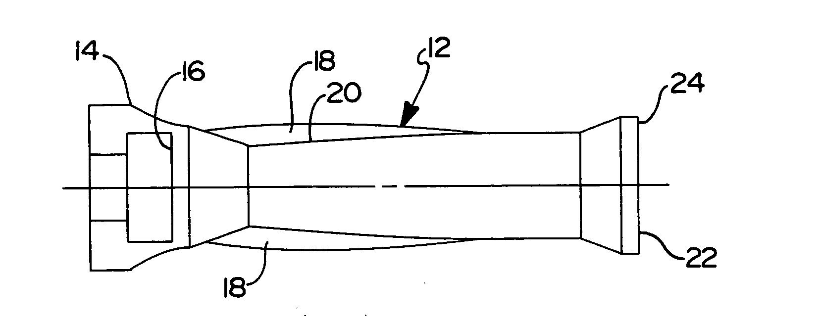
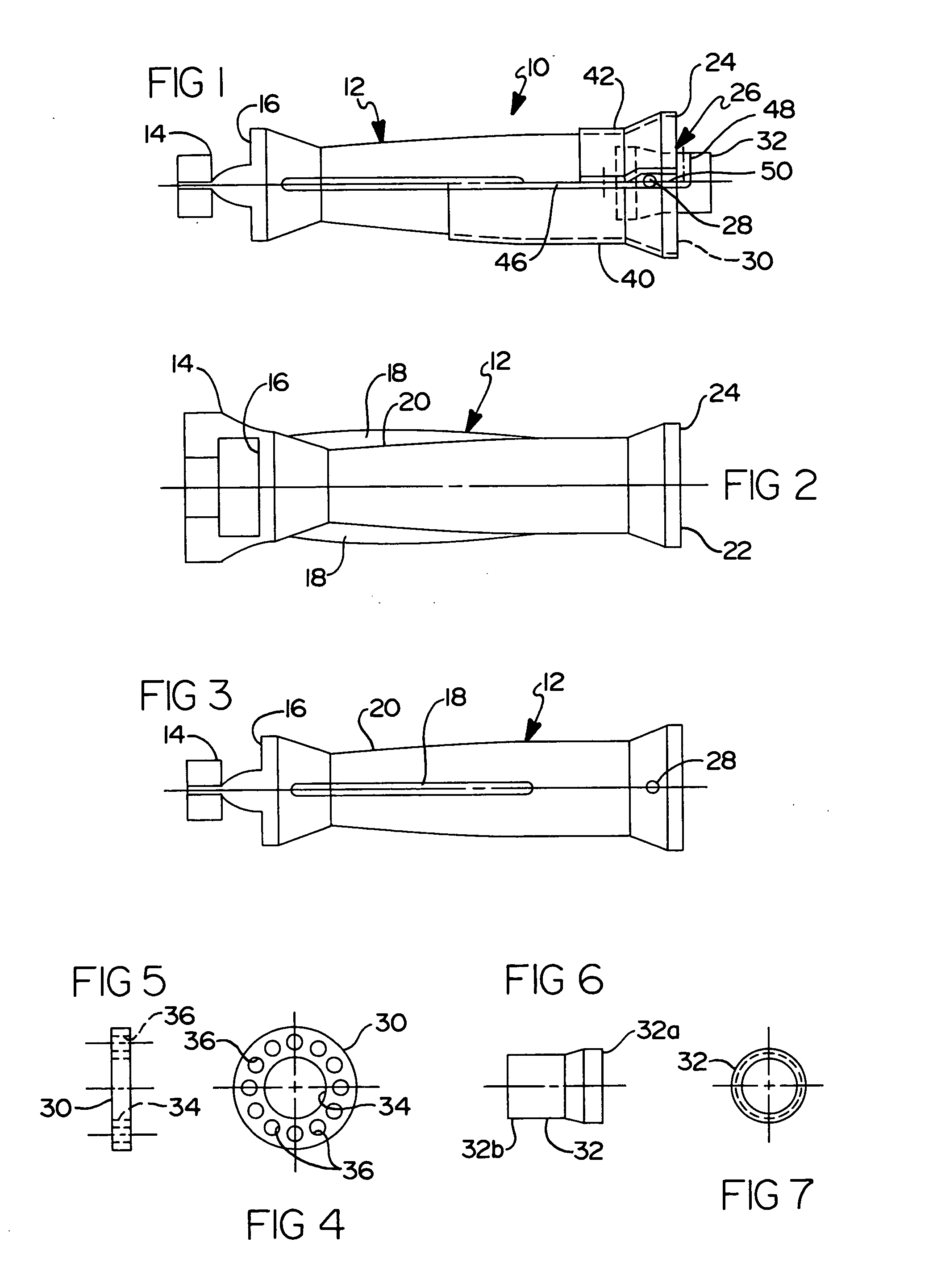
[0023] With reference to FIG. 1, an inshot burner 10, according to the principles of the present invention, is shown. The burner 10 has five component parts that make up the complete assembly. A burner body 12, as best illustrated in FIGS. 2 and 3 is fabricated from a one inch illuminized tube having a 0.065 inch thickness wall. An inch and a half from the back of the tube 12, a reduced diameter portion 14 is provided to create a special shape for the air intake 16. A bead 18 is formed on opposite sides of the burner body in the area of a reduced diameter portion 20. The beads 18 are used to locate the burner body 12, as will be described in greater detail herein. The back of the tube 14 is formed to locate the back of the burner 10 over an orifice that feeds gas to the burner and also forms a window for the primary...


PUM


Abstract

An inshot burner is provided including a burner body and a nozzle assembly provided in an outlet opening of the burner body. The nozzle assembly includes a disc-like member having a central hole therein and a plurality of radially spaced holes spaced around a perimeter of the central hole. A tube member is disposed in the central hole of the disc-like member.

Description

FIELD OF THE INVENTION [0001] The present invention relates to inshot burners and more particularly an inshot burner with an improved construction. BACKGROUND AND SUMMARY OF THE INVENTION [0002] Inshot burners are used to blend a mixture of air and a gaseous fuel to present a combustible product for ignition and flow through a heat exchanger employed in a furnace for heating air. The inshot burner utilizes a mixing tube arranged in conjunction with a nozzle for supplying a gaseous fuel so that the energy in the gaseous fuel is used to induce a flow of air from the ambient into the tube in proportions designed to provide a desired mixture of fuel and air. [0003] Inshot gas burners, such as used in furnaces, typically include a venturi tube which diverges from its input end to an enlarged output end. In some constructions, a burner head insert made of sintered or powered metal having outlet openings is mounted in the outlet end of the tube. In operation, gas is injected into the inlet...

Claims


Application Information

Patent Timeline
IPC IPC(8): F23D5/00F23D14/08F23D14/74
CPCF23D14/08F23D2210/00F23D14/74
Inventor HAWKINS, SAMUEL D.BLOUNT, JOHN L.HAPNER, THOMAS R.
Owner MUELLER IND INC
Why Eureka
Try Eureka