Primary and supplemental intraocular lens

a technology of intraocular lenses and supplementary lenses, which is applied in the field of intraocular lenses, can solve the problems of high risk of inaccuracy, difficult and inaccurate procedures, and insufficient spacing of precise corrective power selection by physicians, and achieve the effect of inhibiting the formation of cellular deposits and sufficient spacing

Inactive Publication Date: 2005-02-03
ADVANCED MEDICAL OPTICS
View PDF42 Cites 110 Cited by
  • Summary
  • Abstract
  • Description
  • Claims
  • Application Information

AI Technical Summary

Benefits of technology

[0016] The supplemental intraocular lens may be either connected to, or separate from, the primary intraocular lens. In one advantageous embodiment, the supplemental intraocular lens is connected to and anteriorly vaulted with respect to the primary intraocular lens. The anterior vaulting of the supplemental intraocular lens allows for sufficient spacing between the two lenses to inhibit the formation of cellular deposits.

Problems solved by technology

When the natural lens loses its ability to clearly focus the image onto the retina through, for example, cataracts or injury, the quality of the focused image on the retina can be severely comprormised.
This procedure can be difficult and inexact.
Errors in measurement, inaccuracy of assumptions, and the difficulty of achieving precise placement of an intraocular lens make the physician's selection of an exact corrective power highly prone to inaccuracies.
Post-operative changes to the patient's eye may also change the refractive power needed for the intraocular lenses in the patient.
Consequently, the intraocular lens, after implantation, does not always provide a perfect vision correction.
Needless to say, this conventional subsequent surgery procedure can be traumatic to the eye.
These various securing means, however, can be complex and difficult to manufacture and implement.
Additionally, the sizes of these supplemental intraocular lenses are often unnecessarily large, thus requiring a larger incision and more trauma to the eye.
Such deposits could result in opacification of the optics and impairment of vision.
Thus, the combined thicknesses of a primary intraocular lens and a supplemental refractive intraocular lens may be too much for the confined space within the anterior or posterior chambers of the eye.
Furthermore, thick supplemental lenses require relatively long surgical incisions.

Method used


Image

  • Primary and supplemental intraocular lens
  • Primary and supplemental intraocular lens
  • Primary and supplemental intraocular lens

Examples


Embodiment Construction

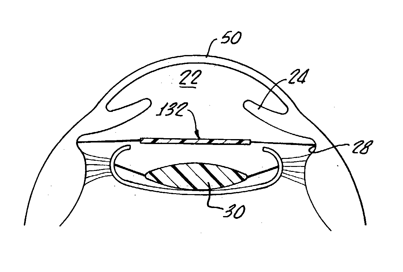
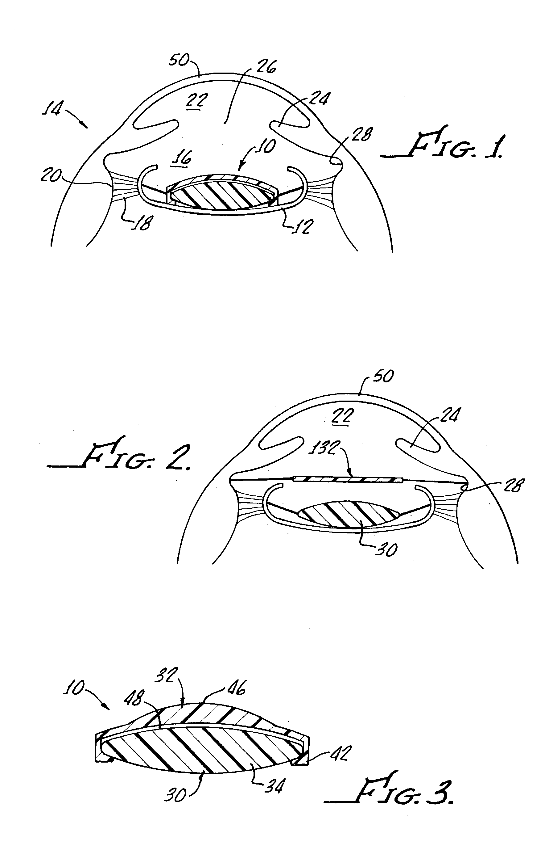
[0026] Referring to the drawings in more detail, FIG. 1 shows an intraocular lens system 10 according to the present invention implanted in the capsular bag 12 of an eye 14. The capsular bag 12 is held in the posterior chamber 16 of the eye 14 by a set of suspensory ligaments or zonules 18 that extend between the capsular bag 12 and an annular ciliary muscle 20. The posterior chamber 16 is separated from the anterior chamber 22 of the eye 14 by an annular iris 24, which defines the variable opening or aperture known as the pupil 26. The iris is separated from the ciliary muscle by an annular groove known as the sulcus 28.

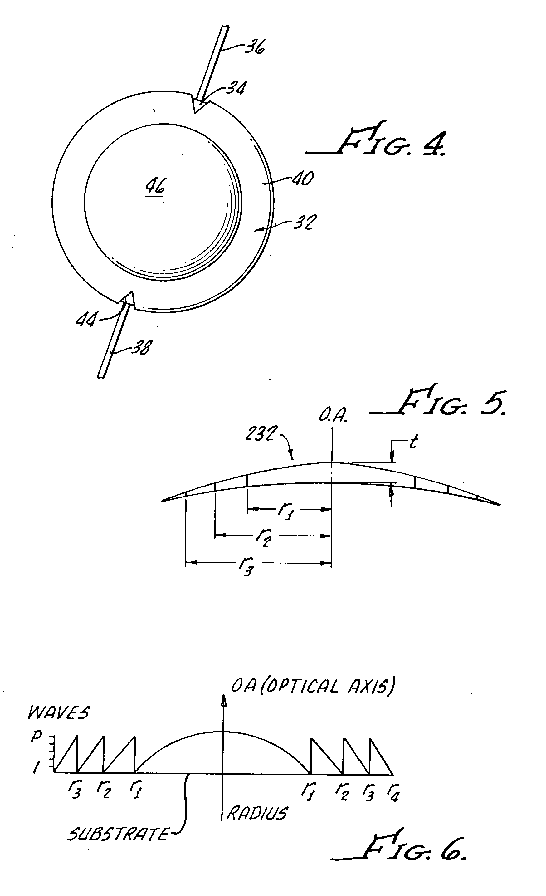
[0027] Turning now to FIGS. 3 and 4, the intraocular lens system 10 includes a primary intraocular lens 30 that is configured to correct the vision of a patient, and a supplemental intraocular lens 32 that is configured to modify the correction of the primary intraocular lens 30. The supplemental intraocular lens 32 may be implanted simultaneously with the primary ...


PUM


Abstract

An intraocular lens system includes a primary intraocular lens configured to correct vision in a patient, and a supplemental intraocular lens configured to modify the correction provided by the primary intraocular lens. The supplemental intraocular lens, which is substantially completely diffractive, is preferably ultrathin. The two lenses may be connected to, or separate from, one another. The supplemental intraocular lens may be implanted at the same time as the primary intraocular lens, or added later.

Description

FIELD OF THE INVENTION [0001] This invention relates generally to intraocular lenses and, more particularly, to supplemental intraocular lenses, which can be placed in, on, or near primary intraocular lenses to change the effective optical power of the primary intraocular lens. BACKGROUND OF THE INVENTION [0002] Vision is achieved in the human eye by transmitting an image through a clear outer portion called the cornea, and focusing this image via a natural lens onto a retina. [0003] When the natural lens loses its ability to clearly focus the image onto the retina through, for example, cataracts or injury, the quality of the focused image on the retina can be severely comprormised. [0004] An accepted treatment for a damaged natural lens is surgical removal of the natural lens and replacement of the natural lens with an artificial intraocular lens. One way to accomplish this procedure is to form a relatively long incision in the eye and remove the natural lens in one piece. A more p...

Claims


Application Information

Patent Timeline
Patent Type & Authority Applications(United States)
IPC IPC(8): A61F2/16
CPCA61F2/1613A61F2250/0036A61F2/1654A61F2/1648A61F2/1602
Inventor BRADY, DANIEL G.ROCKLEY, PAUL
Owner ADVANCED MEDICAL OPTICS
Why Eureka
Try Eureka