

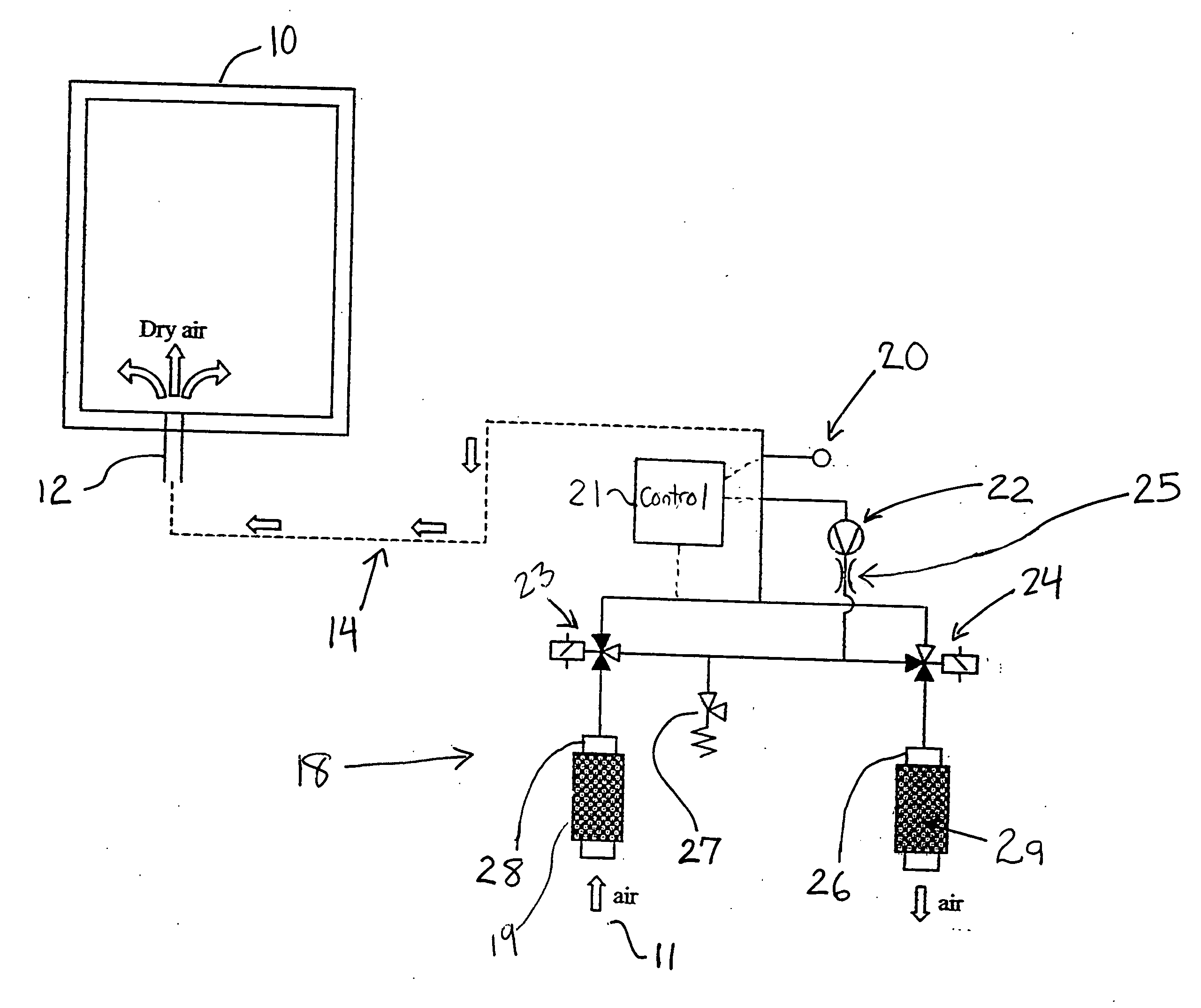
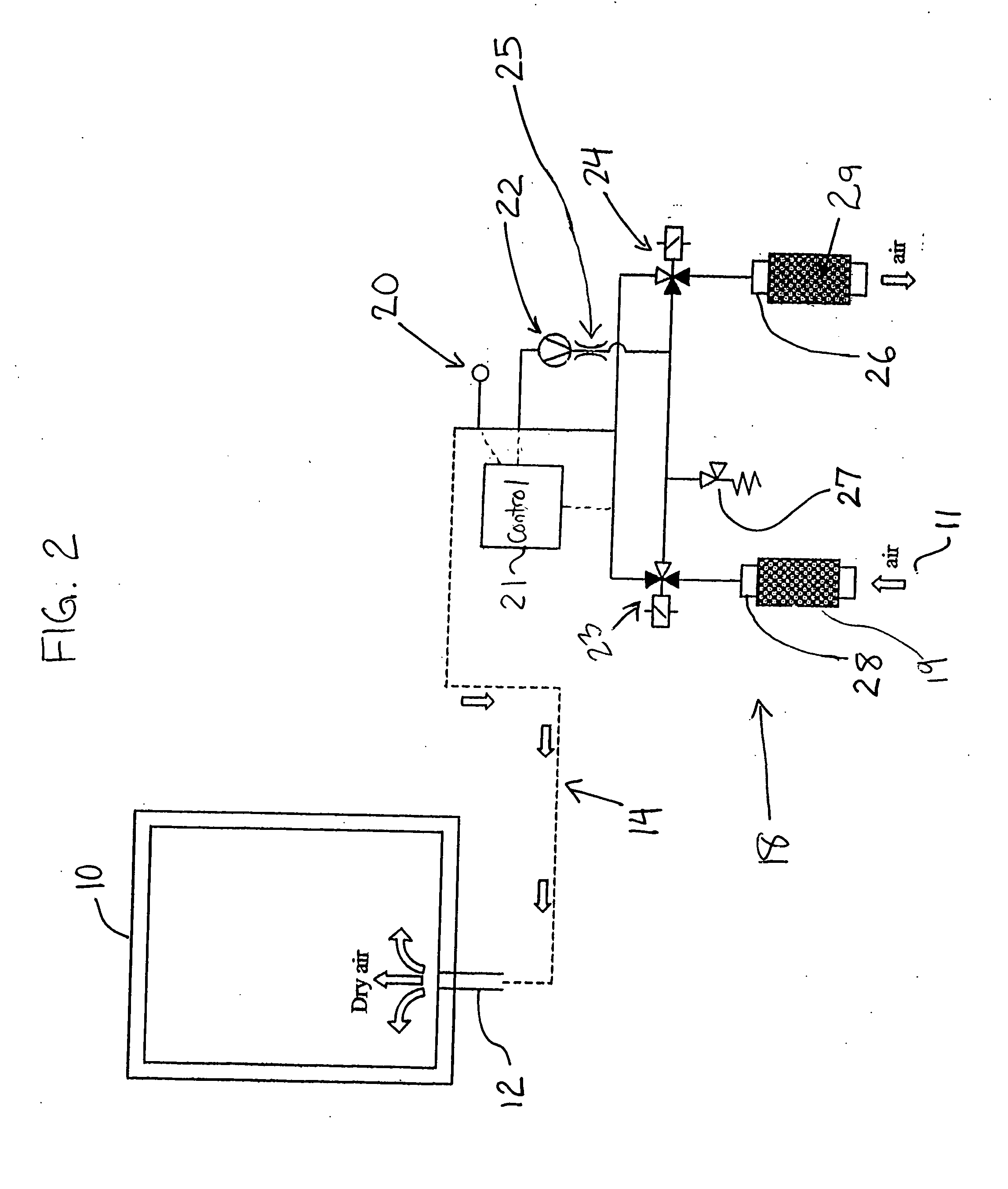
Dryer system for the prevention of frost in an ultra low temperature freezer
a freezing and ultra-low temperature technology, applied in the direction of defrosting, domestic cooling apparatus, application, etc., can solve the problem that the time period cannot be controlled by the known apparatus, and achieve the effect of fast return delivery, space saving, and rapid return delivery
- Summary
- Abstract
- Description
- Claims
- Application Information
AI Technical Summary
Benefits of technology
Problems solved by technology
Method used
Image

Examples
Embodiment Construction
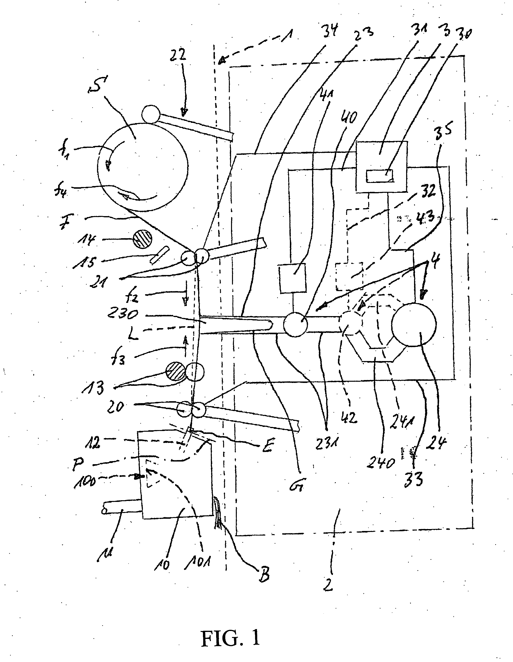
Reference will now be made in detail to the presently claimed embodiments of the invention, one or more examples of which are shown in the figure. Each example is provided to explain, and not is a limitation of the invention. In fact, features illustrated or described as part of one embodiment can be used with another embodiment to yield still a further embodiment. It is intended that the present invention cover such modifications and variations.
An open-end spinning machine (1) is depicted by a dotted line, shown at the left in FIG. 1. This machine possesses, as a rule, a multiplicity of similarly designed open-end spinning apparatuses 10, which are in communication with a suction line 11 and have a spinning element 100. The said spinning element 100, throughout this discussed embodiment, is designed as a spin rotor.
Other designs of the spinning element, such as, for example: an electrostatically operated spinning element; an air spinning element; a friction spinning element...
PUM
 Abstract
Description
Claims
Application Information