Method of manufacturing a liquid ejecting head

a technology of liquid ejector and manufacturing method, which is applied in the manufacture of printed circuits, printing circuits, printed circuits, etc., can solve the problems of increased production costs, ink-discharging problems, and inability to detect dots, so as to improve the fluidity of resin materials.

Active Publication Date: 2012-12-18
SEIKO EPSON CORP
View PDF5 Cites 0 Cited by
  • Summary
  • Abstract
  • Description
  • Claims
  • Application Information

AI Technical Summary

Benefits of technology

[0010]An advantage of some aspects of the invention is to provide a liquid ejecting head that makes it possible to reduce production costs. The invention further provides, as an advantage of some aspects thereof, a method for manufacturing such a liquid ejecting head and a liquid ejecting apparatus that is provided with such a liquid ejecting head.
[0012]With such a manufacturing method, it is possible to fix the first supply member and the second supply member to each other simultaneously (where either the first supply member or the second supply member may be made up of a plurality of member elements) by means of the molded fixation member through a single resin injection process in which a resin material is filled. Therefore, it is not necessary to individually fix the first supply member and the second supply member to each other one by one. Thus, it is possible to simplify a manufacturing process to reduce production costs. In addition, since convexes / concaves are formed on / in the surface of the fixation member, it is possible to determine the position of a liquid container or other members and the attachment height thereof with the use of the concaves and the convexes and then attach the liquid container or the like to the first supply member and the second supply member with high attachment precision.
[0013]Moreover, since the first supply member and the second supply member are fixed into a single-piece member as a result of the mold formation of the fixation member, it is not necessary to provide individual filter-attachment areas for attaching the filtering member to the first supply member and the second supply member. With such a structure, it is possible to increase the effective filtering area of the filtering member and shorten an interval between each two member elements of the first supply member or the second supply member that are arrayed adjacent to each other. For this reason, it is possible to reduce the size of a liquid ejecting head. Furthermore, since it is not necessary to decrease the area size of the filtering member in order to achieve the head-size reduction, dynamic pressure does not increase. Therefore, it is not necessary to increase a driving voltage, which is used for driving a pressure generation means such as a piezoelectric element, a heating element, or the like. Moreover, the fixation member prevents the formation of a gap between the first supply member and the second supply member. Therefore, the leakage of liquid through the gap would not occur.
[0014]In the method for manufacturing a liquid ejecting head according to the first aspect of the invention, it is preferable that the convex and the concave should be formed concurrently with the molding of the fixation member. With such a preferred manufacturing method, since the convex and the concave are formed in the same process as the formation of the fixation member, it is possible to make a series of manufacturing processes simpler in comparison with a case where the convex and the concave are formed in a separate formation process, that is, not concurrently with the molding of the fixation member.
[0016]In the method for manufacturing a liquid ejecting head according to the first aspect of the invention, it is preferable that the fixation member should be molded in such a manner that the liquid supply passage only penetrates through the fixation member. With such a preferred manufacturing method, the fluidity of a resin material improves. The resin material flows without being obstructed and is filled throughout the entire area where the fixation member is to be formed. Thus, it is possible to form the fixation member that has adequate strength in a reliable manner.

Problems solved by technology

As a result, the ink-discharging performance of the ink jet recording head could deteriorate.
For example, missing dots, which is an ink-discharging problem, could occur due to the undesirable presence of air bubbles in ink retained inside the head body.
Since the plurality of ink-supply needles has to be fixed thereto individually, the manufacturing process thereof is not efficient, which increases production costs.
That is, the same problems could also arise in various kinds of liquid ejecting heads.

Method used


Image

  • Method of manufacturing a liquid ejecting head
  • Method of manufacturing a liquid ejecting head
  • Method of manufacturing a liquid ejecting head

Examples


first embodiment

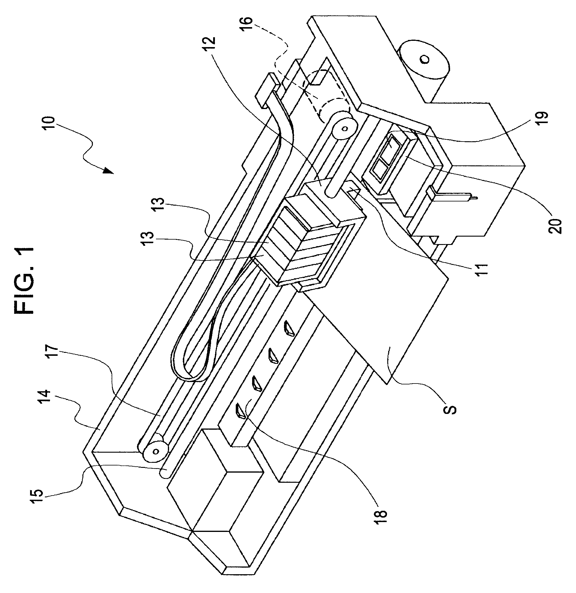
[0029]FIG. 1 is a perspective view that schematically illustrates an example of the configuration of an ink jet recording apparatus, which is an example of various kinds of liquid ejecting apparatuses according to a first embodiment of the invention. As illustrated in FIG. 1, an ink-jet recording apparatus 10 according to the present embodiment of the invention is provided with an ink jet recording head 11 that discharges ink drops. The ink jet recording head 11 is an example of various kinds of liquid ejecting heads according to an aspect of the invention. The ink jet recording apparatus 10 is further provided with a carriage 12 to which the ink jet recording head 11 is fixed. Ink cartridges 13, each of which constitutes an example of a liquid container according to an aspect of the invention, are detachably attached to the ink-jet recording head 11. Each of these ink cartridges 13 contains ink that has the corresponding one of a set of ink colors, for example, black (B) [K], light...


PUM

PropertyMeasurementUnit
moldingaaaaaaaaaa
pressureaaaaaaaaaa
timeaaaaaaaaaa

Abstract

A method for manufacturing a liquid ejecting head is provided. The liquid ejecting head has nozzle openings and ejects liquid supplied through a liquid supply passage from the nozzle openings. The manufacturing method includes: disposing a filtering member between a first supply member and a second supply member, the first supply member having one part of the liquid supply passage formed therein, the second supply member having the other part or another part of the liquid supply passage formed therein, the second supply member being disposed over one surface of the first supply member; and injecting a resin material over the one surface of the first supply member to cover a part of the second supply member for molding a fixation member and fixing the first supply member and the second supply member into a single-piece member as a result of the molding, wherein a convex is formed on a surface of the fixation member in the mold fixation of the first supply member and the second supply member, and a concave is formed in the surface of the fixation member in the mold fixation of the first supply member and the second supply member.

Description

[0001]This application claims priority to Japanese Patent Application No. 2008-252,662, filed Sep. 30, 2008, the entirety of which is incorporated by reference herein.BACKGROUND[0002]1. Technical Field[0003]The present invention generally relates to a liquid ejecting head that ejects liquid, a method for manufacturing a liquid ejecting head, and a liquid ejecting apparatus that is provided with a liquid ejecting head. More particularly, the invention relates to an ink-jet recording head that discharges ink as an example of various kinds of liquid, a method for manufacturing an ink-jet recording head, and an ink-jet recording apparatus that is provided with an ink-jet recording head.[0004]2. Related Art[0005]An ink-jet recording head, which is an example of various kinds of liquid ejecting heads, has the following configuration and ejects ink as follows. Ink is contained in ink cartridges, which are detachably attached to a cartridge case. When the ink cartridges are detachably attac...

Claims


Application Information

Patent Timeline
Patent Type & Authority Patents(United States)
IPC IPC(8): B21D53/76B29C45/14
CPCB41J2/161B41J2/1623B41J2/1637B41J2/17563Y10T29/49158B41J2002/14362Y10T29/49401Y10T29/49146
Inventor KAMIKURA, HIROYUKIOWAKI, HIROSHIGENAKAMURA, KAZUHIDE
Owner SEIKO EPSON CORP
Why Eureka
Try Eureka