Flow-monitoring method and device

a flow monitoring and flow measurement technology, applied in the direction of measuring devices, volume/mass flow by dynamic fluid flow effect, instruments, etc., can solve the problems of large installation site, high initial cost, and high power requirements of prior art systems, and achieve cost effective installation

Inactive Publication Date: 2005-02-10
AQUA SYST 2000
View PDF29 Cites 24 Cited by
  • Summary
  • Abstract
  • Description
  • Claims
  • Application Information

AI Technical Summary

Benefits of technology

[0009] It is an object of the present invention to overcome the disadvantages of previous flow-monitoring methods and devices. In particular, it is an object of the present invention to provide a method and device which can be cost effec

Problems solved by technology

Many of these prior art flow-measuring systems are installed in larger sites and are not designed for or effective in measuring or metering fluid flow and typically require finely-tuned parts to continuously measure flow for determining total flow for a specific time period.
Further, many prior art systems require high upkeep, have high power requirements, are not portable or have a high initial cost.
Another problem experienced by prior art flow-measuring systems is that the

Method used


Image

  • Flow-monitoring method and device
  • Flow-monitoring method and device
  • Flow-monitoring method and device

Examples


Embodiment Construction

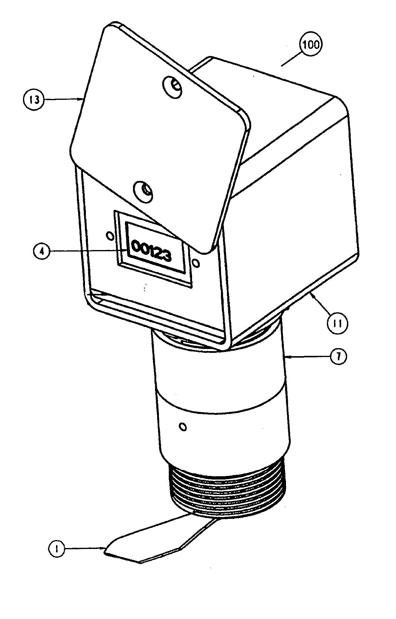
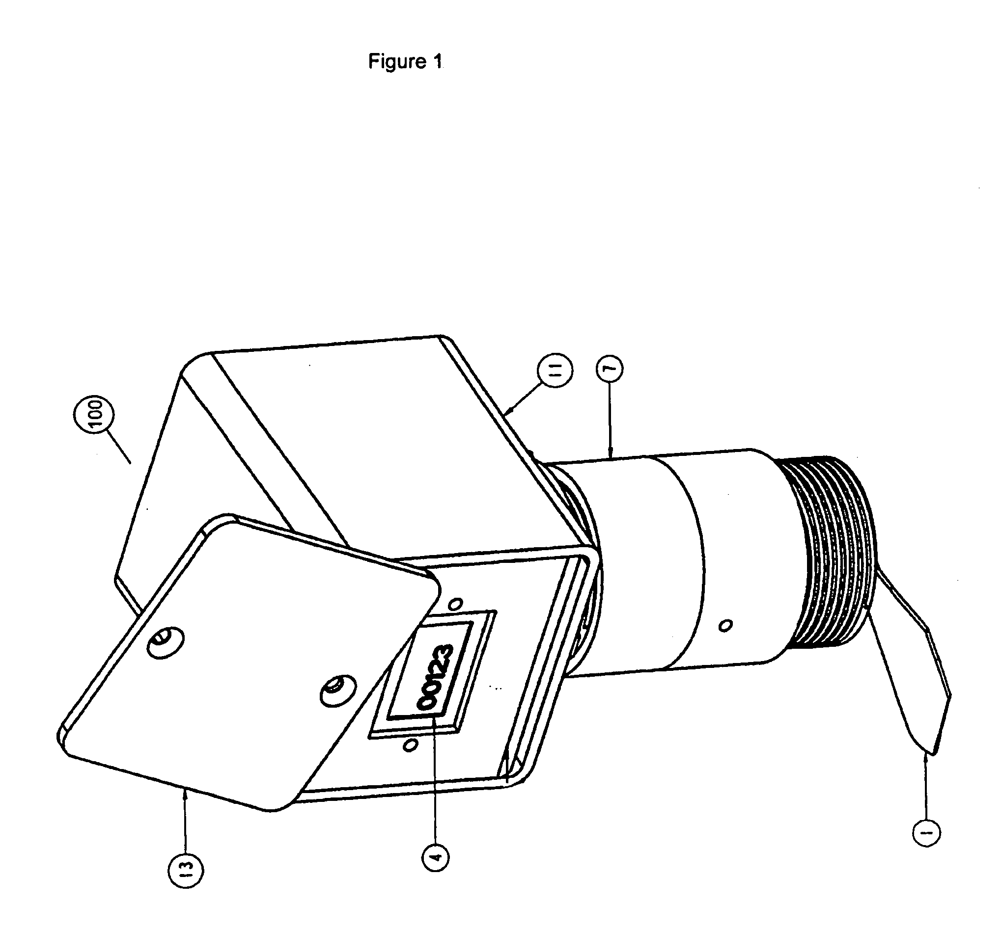
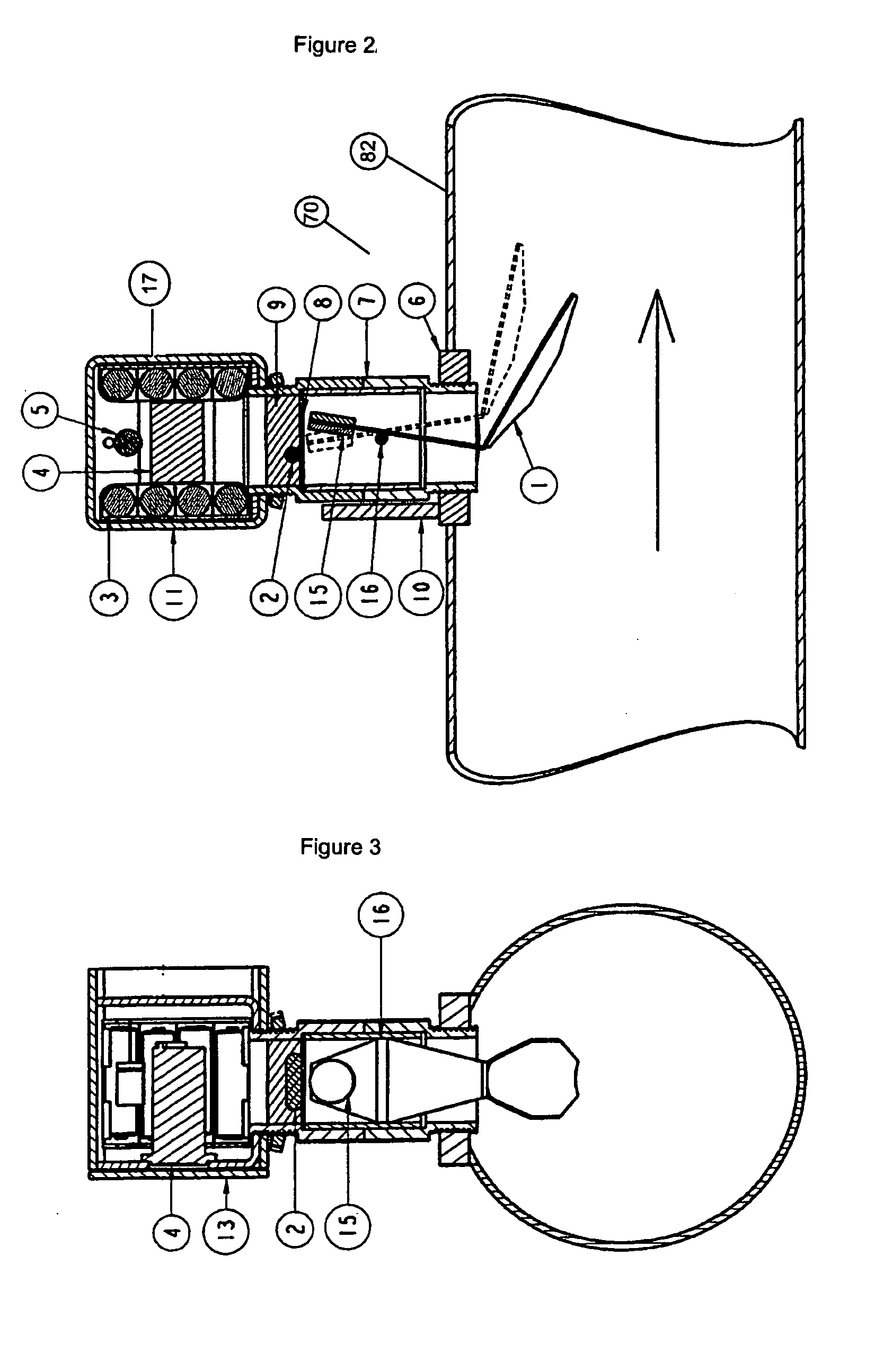
[0024] Generally, the present invention provides a method and device for monitoring the flow of fluids through a pipeline 82, channel 83 or other supply or conduit system. With reference to FIG. 1, a flow-monitoring device 100 includes a sensor system 70 and a counter or metering system 11 which includes a memory (not shown), record-making means (not shown) and a clock or elapsed-time measuring means 4. The device 100 is installed and positioned in a closed pipeline 82 or an open channel 83 such that when water or fluid is flowing through the pipeline 82 or channel 83, the sensor system 70 will be in fluid communication with the fluid supply. In general operation, when the fluid is flowed through the pipeline or the channel, the sensor system 70, in communication with the counter system 11, will activate the counter system 11. The counter system 11 records the amount of time during which the counter system 11 is activated (which has the effect of metering the time during which the f...


PUM


Abstract

A flow-monitoring method and device for measuring the flow of fluid through a conduit such as a pipeline or open channel. More particularly, the present invention relates to a method and device for monitoring fluid flow for metering purposes. In one embodiment, the device includes a sensor system in communication with a counter system. In a further embodiment, the sensor system includes a vane moveable between an activated and a deactivated position. When fluid flows past the vane, the vane is moved into an activated position and the sensor system in turn activates the counter system for recording the length of time during which fluid is being supplied through the pipeline or channel. When fluid is no longer supplied, the vane reverts to a deactivated position which signals the sensor system to turn off the counter system.

Description

CROSS-REFERENCE TO RELATED APPLICATIONS [0001] This application claims the benefit of U.S. patent application Ser. No. 60 / 487,611, filed Jul. 17, 2003, which is incorporated herein by reference in its entirety.FIELD OF THE INVENTION [0002] The present invention relates generally to a flow-monitoring method and device for recording the duration of the flow of fluids through a conduit such as a pipeline or open channel. More particularly, the present invention relates to a method and device for monitoring water or liquid flow for metering purposes. BACKGROUND OF THE INVENTION [0003] It is generally desirable for businesses and organizations supplying fluids such as water or other liquids through pipeline systems or channels to be able to accurately and cost effectively measure the quantities they provide to be able to charge recipients of the supplied fluids appropriately. More specifically, it is becoming increasingly important to quantify the amount of water provided to individuals ...

Claims


Application Information

Patent Timeline
IPC IPC(8): G01F1/28
CPCG01F1/28
Inventor LANGEMANN, PETER J.CRAIG, KENNETH R.
Owner AQUA SYST 2000
Why Eureka
Try Eureka