Injection system and casting method of die casting machine

a technology of injection system and die casting machine, which is applied in the direction of manufacturing tools, filing appliances,foundry moulding apparatus, etc., can solve the problems of increased cost and time-consuming work

Active Publication Date: 2005-02-10
TOSHIBA MASCH CO LTD
View PDF8 Cites 35 Cited by
  • Summary
  • Abstract
  • Description
  • Claims
  • Application Information

AI Technical Summary

Benefits of technology

[0008] An object of the present invention is to provide an injection system and casting method of a die casting machine giving a required casting pressure without adjusting the accumulator side even if the injection system has to change the finally output casting pressure due to the exchange of dies or changes in the casting conditions.

Problems solved by technology

This work required time.
Further, adjustment of the pressure of the accumulator required the discharge or discharge of the nitrogen gas, so there was also the disadvantage of the higher cost.

Method used


Image

  • Injection system and casting method of die casting machine
  • Injection system and casting method of die casting machine
  • Injection system and casting method of die casting machine

Examples


Embodiment Construction

[0024] Preferred embodiments of the present invention will be described in detail below with reference to the accompanying drawings.

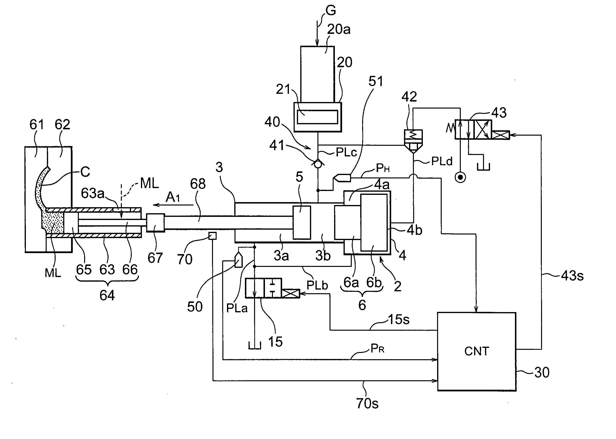
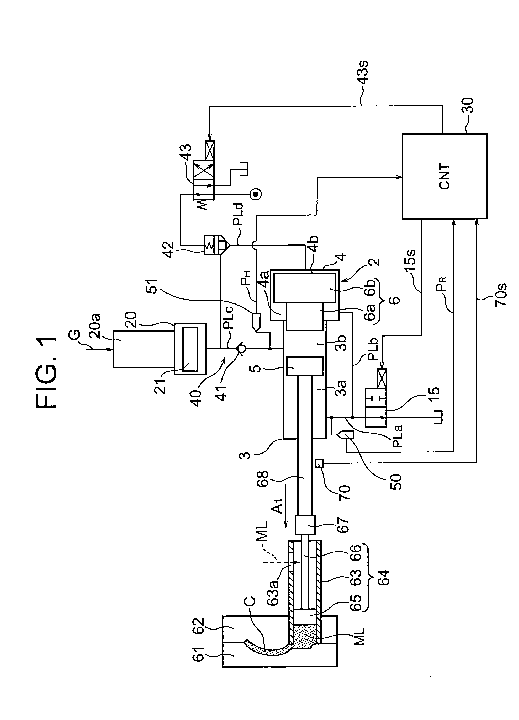
[0025]FIG. 1 is a view of the configuration of an injection system of a die casting machine according to an embodiment of the present invention. The injection system 1 shown in FIG. 1 has an injection cylinder 2, an accumulator 20, an oil pressure circuit 40, a control valve 15, a control apparatus 30, first and second pressure detectors 50 and 51, an injection plunger 64, and an injection sleeve 63. The injection cylinder 2 is an embodiment of the injection cylinder of the present invention, the accumulator 20 the accumulator of the present invention, the oil pressure circuit 40 the liquid pressure circuit of the present invention, the control valve the control valve of the present invention, the control apparatus 30 the control means of the present invention, the pressure detector 50 the first pressure detecting means of the present invention, and th...


PUM

PropertyMeasurementUnit
pressureaaaaaaaaaa
flow rateaaaaaaaaaa
pressuresaaaaaaaaaa

Abstract

An injection system of a die casting machine giving the necessary casting pressure without adjusting the accumulator side, provided with an injection cylinder including an injection piston linked with the injection plunger and a booster piston arranged behind the injection piston, an accumulator for supplying a pressurized liquid of a predetermined pressure, a liquid pressure circuit for supplying the pressurized liquid from the accumulator to the injection cylinder, driving the injection piston, then driving the booster piston, a control valve for controlling a flow rate of the pressurized liquid discharged from the front side of the injection piston of the injection cylinder so as to control a flow rate of the injection piston, and controlling the pressure of the pressurized liquid at the front side of the injection piston by the timing of closing the control valve to determine the final value of the casting pressure.

Description

BACKGROUND OF THE INVENTION [0001] 1. Field of the Invention [0002] The present invention relates to an injection system and casting method of a die casting machine method. [0003] 2. Description of the Related Art [0004] In a die casting machine, an injection plunger is used to inject a molten metal into a cavity of a die by an injection plunger. The quality of the cast product greatly depends upon the injection speed of the molten metal and the casting pressure (injection pressure). Therefore, it is necessary to suitable control the speed of movement (injection speed) and pressure of the injection cylinder driving the injection plunger. That is, the injection speed and the casting pressure (injection pressure) are controlled in accordance with the state of filling the molten metal between the casting cycles to realize the optimal injection operation. [0005] For example, in a predetermined zone after the start of injection, the injection plunger is made to move by a low injection sp...

Claims


Application Information

Patent Timeline
Patent Type & Authority Applications(United States)
IPC IPC(8): B22D17/20B22D17/04B22D17/32
CPCB22D17/32B42F3/003B42F7/025B42P2241/02
Inventor TOYOSHIMA, TOSHIAKIABE, YUJIYOKOYAMA, HIROSHITSUJI, MAKOTO
Owner TOSHIBA MASCH CO LTD
Why Eureka
Try Eureka