Impact drill
a drill bit and impact technology, applied in the field of impact drill bit, can solve the problems of prone to breaking of the rear end b, 522/b>/i>d /i>or the plate b>524/b>, and the transmission of the vibration to the handle cannot be avoided, so as to reduce the transmission of the vibration to the user and minimize the effect of the transmission of the vibration
- Summary
- Abstract
- Description
- Claims
- Application Information
AI Technical Summary
Benefits of technology
Problems solved by technology
Method used
Image

Examples
first embodiment
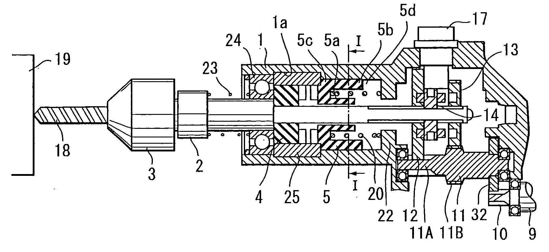
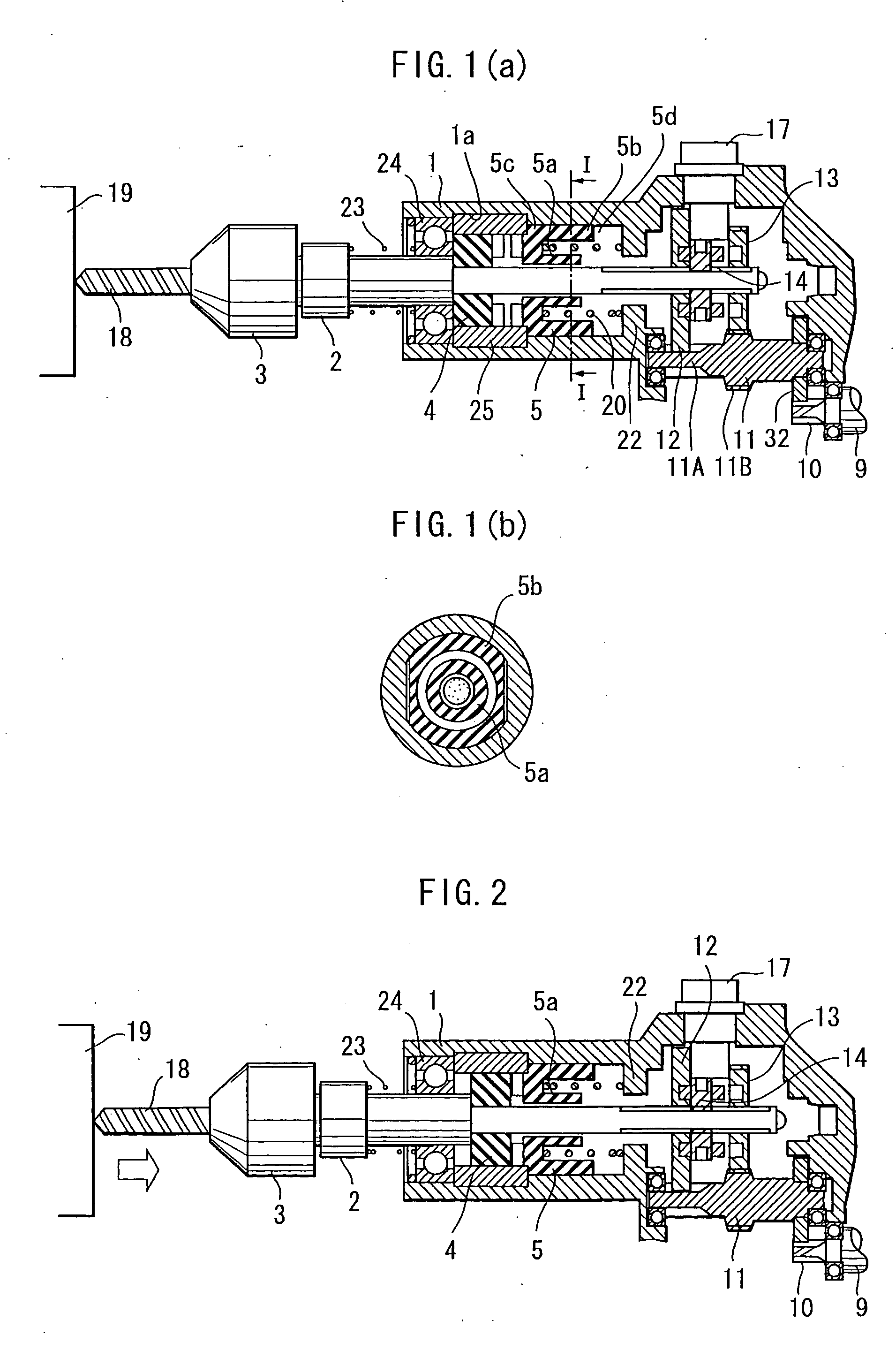
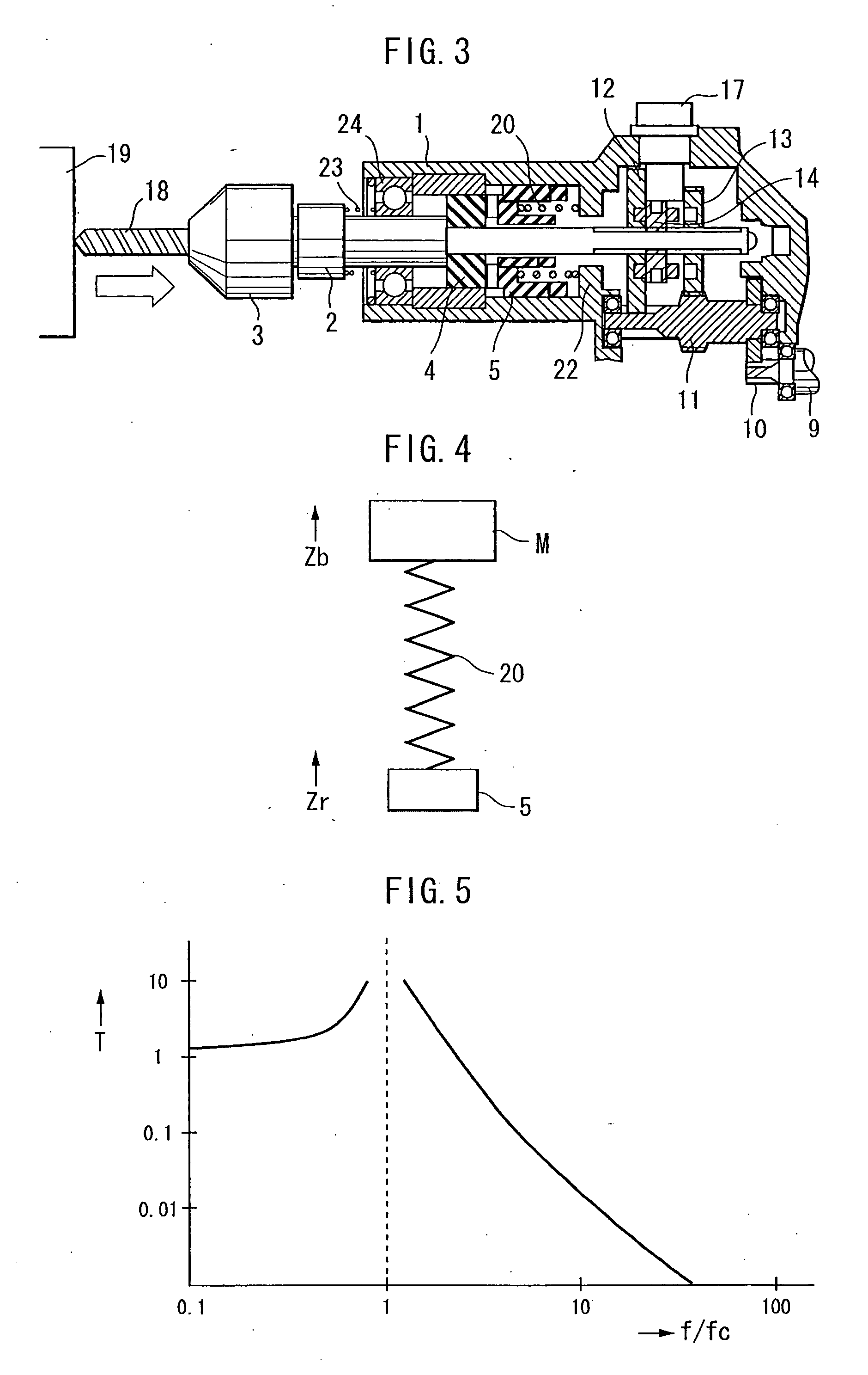
[0045] An impact drill according to the present invention will be described with reference to FIGS. 1 through 5. A main frame 1 supports a spindle 2 by a bearing 24 such that the spindle 2 is movable forward (leftward in the drawing) and backward (rightward in the drawing) with respect to a workpiece 19. A chuck 3 for securing a bit 18 is disposed on a front tip end of the spindle 2. A spindle spring 23 is interposed between the spindle 2 and an inner race of the bearing 24 for normally biasing the spindle frontward (leftward in FIG. 1). An inner end portion of the spindle 2 is provided with a speed changing mechanism described later.
[0046] A first ratchet 4 and a second ratchet 5 are provided substantially concentrically with the main frame 1. The first ratchet 4 is rotatable and axially movable along with the rotation and axial displacement of the spindle 2. The first ratchet 4 has one surface having a serrated contour or alternating projections and recesses. The main frame 1 is f...
second embodiment
[0062] An impact drill according to the present invention will next be described with reference to FIGS. 6 to 9 wherein like parts and components are designated by reference numerals added with 100 to those shown in FIGS. 1 through 5 to avoid duplicating description.
[0063] In the second embodiment, a member corresponding to the stop member 25 of the first embodiment is dispensed with. Instead, a washer 128 is provided slidably movably along the annular recess 101a of the main frame 101 at a position corresponding to the stop member 25. The annular recess 101a defines an abutment face 101b at its rear end. The washer 128 has an inner diameter greater than an outer diameter of the first ratchet 104 for allowing the first ratchet 104 to enter the washer 128.
[0064] The front end of the second ratchet 105 is abuttable on a rear face of the washer 128. Further, a second spring 121 is interposed between the outer race of the bearing 124 and a front face of the washer 128 for biasing the s...
third embodiment
[0075] In the third embodiment, the second ratchet 205 maintains its floating position in drilling mode as well as impact drilling mode. Furthermore, the vibration passed to the user can be reduced since the vibration caused by the first and second ratchets 204 and 205 is not readily transferred to the main frame 201. In addition, the frictional force acting between the second ratchet 205 and the outer cylinder 205b can be reduced by the rolling of the ball member 229. Therefore, friction loss can be reduced.
[0076] FIGS. 14(a) and 14(b) show an impact drill according to a fourth embodiment of the present invention, wherein like parts and components are designated by reference numerals added with 300 to those of the first embodiment.
PUM
| Property | Measurement | Unit |
|---|---|---|
| force | aaaaa | aaaaa |
| pressing force | aaaaa | aaaaa |
| natural frequency | aaaaa | aaaaa |
Abstract
Description
Claims
Application Information
 - Generate Ideas
- Intellectual Property
- Life Sciences
- Materials
- Tech Scout
- Unparalleled Data Quality
- Higher Quality Content
- 60% Fewer Hallucinations
Browse by: Latest US Patents, China's latest patents, Technical Efficacy Thesaurus, Application Domain, Technology Topic, Popular Technical Reports.
© 2025 PatSnap. All rights reserved.Legal|Privacy policy|Modern Slavery Act Transparency Statement|Sitemap|About US| Contact US: help@patsnap.com