Fish tape winder insert

a winder insert and tape technology, applied in the direction of cables, rigid containers, cables, etc., can solve the problems of requiring significant force, difficult winding and unwinding of tape, virtually impossible to push through long conduit lengths, etc., and achieve the effect of removing the tape quickly and easily

Inactive Publication Date: 2005-02-10
ACTUANT CORP
View PDF25 Cites 4 Cited by
  • Summary
  • Abstract
  • Description
  • Claims
  • Application Information

AI Technical Summary

Benefits of technology

[0015] In still other preferred forms, the sprocket section of the hub has a plurality of sprocket-like structures, preferably three spaced around the center axis at equal angles, sized to engage mating surfaces at the inner periphery of the reel. These sprockets define concave surfaces abutting convex surfaces at the inner periphery of the

Problems solved by technology

Because typical electrical wire is very flexible, pushing it through long lengths of conduit is virtually impossible.
This reel arrangement makes it somewhat difficult to wind and unwind the tape.
Given the relative rigid and springy characteristics of the fish tape, coiling the fish tape can require significant force and can be time consuming and frustrating, particularly if th

Method used


Image

  • Fish tape winder insert
  • Fish tape winder insert
  • Fish tape winder insert

Examples


Embodiment Construction

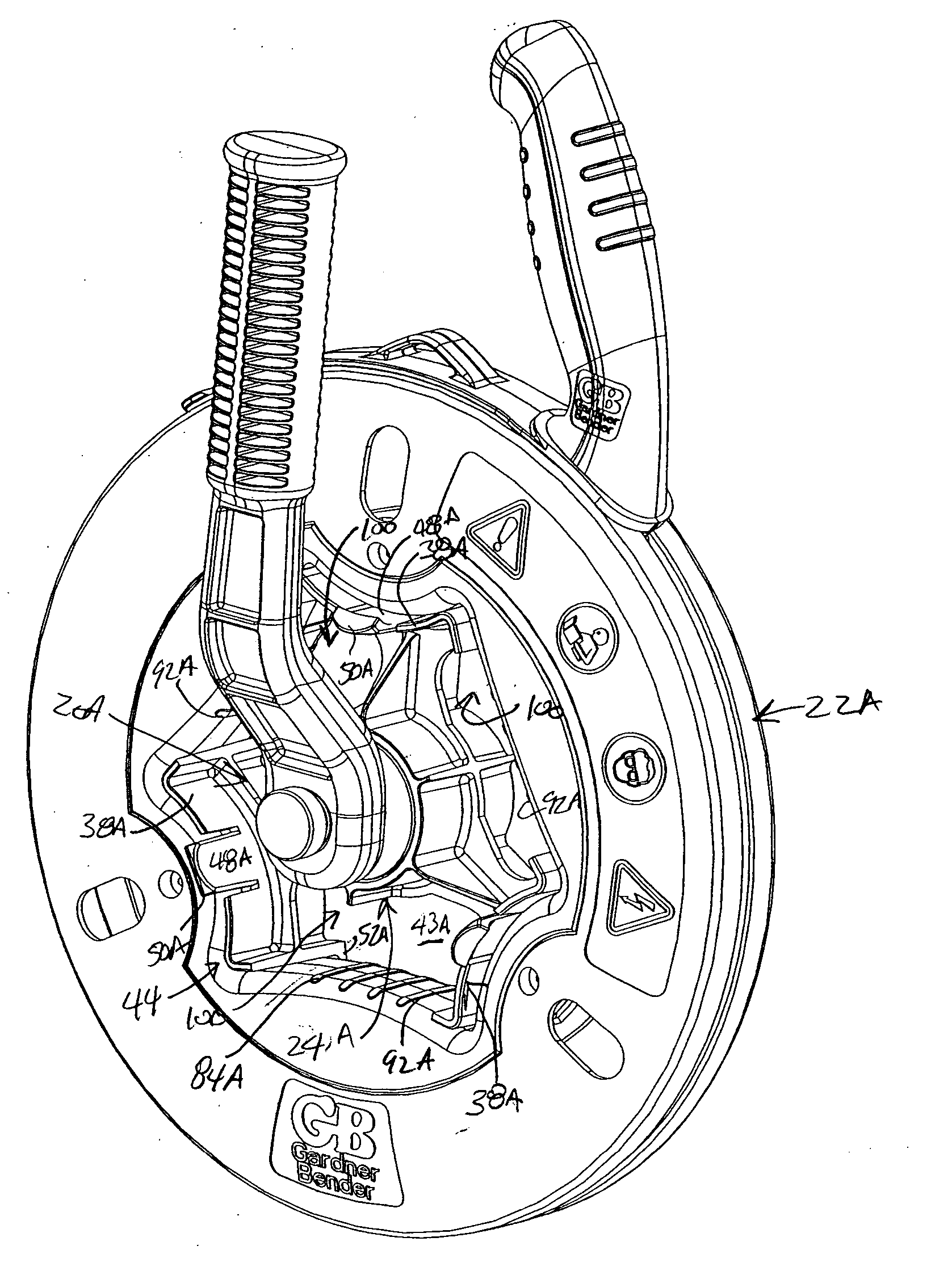
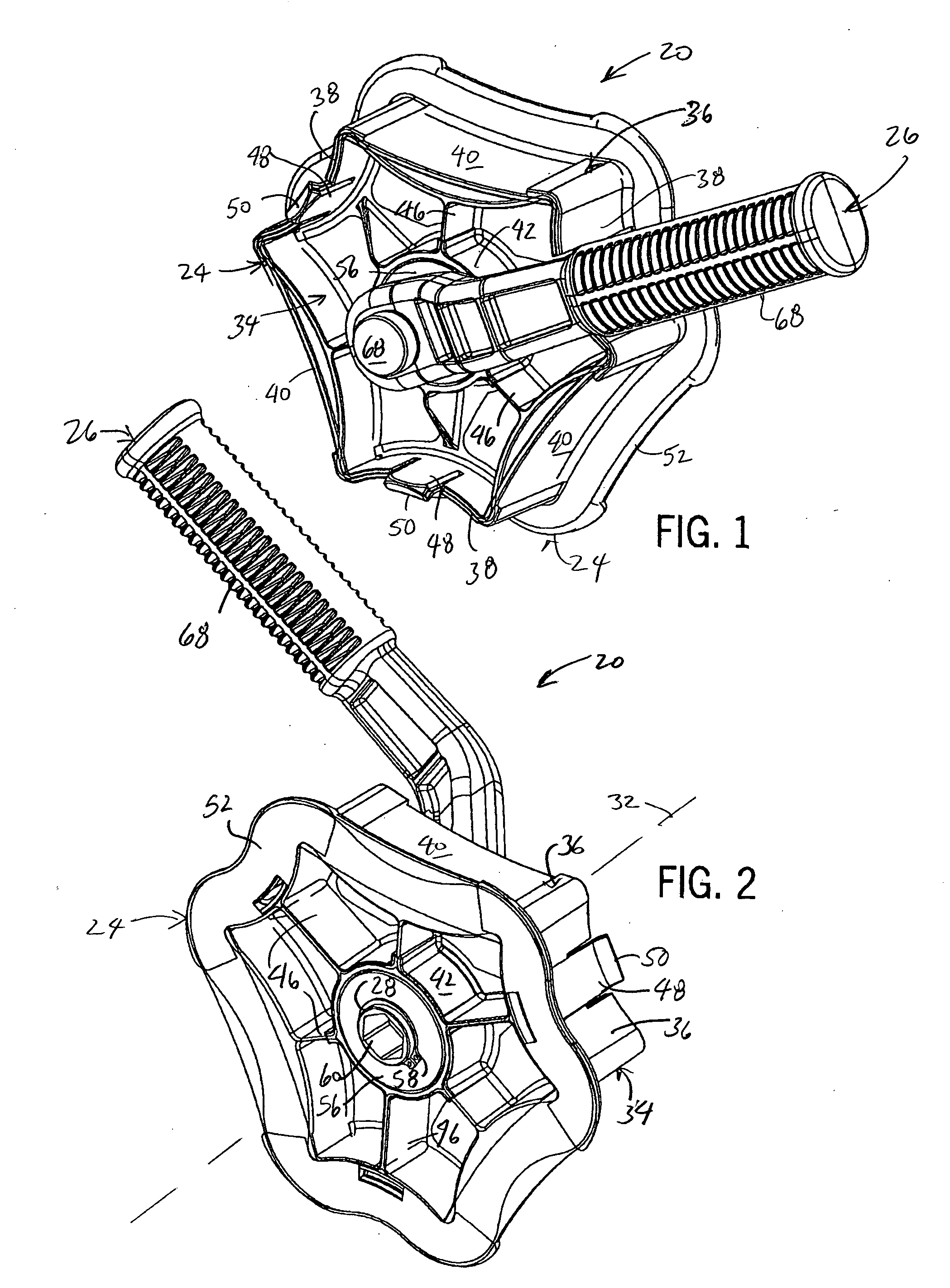
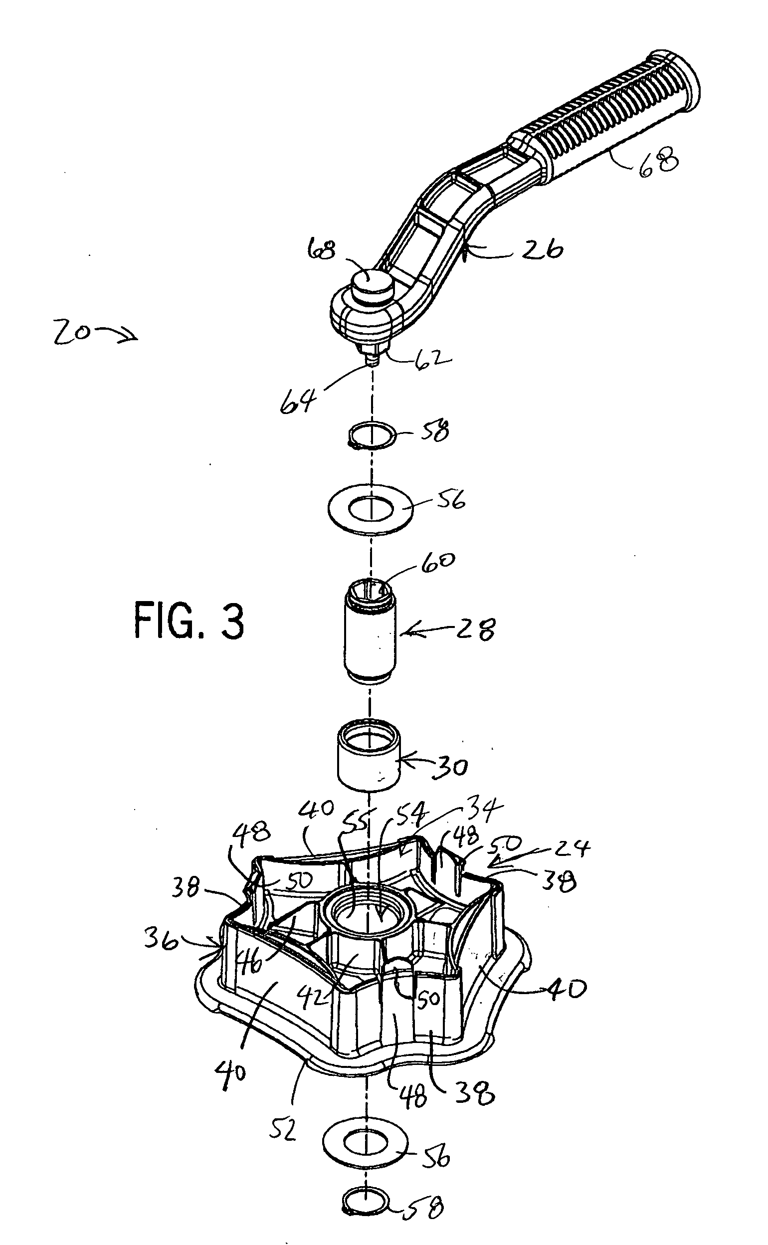
[0030] The drawings referenced herein illustrate a preferred version of a winder insert 20 for a fish tape reel assembly 22 (preferably as shown in FIGS. 9-12). Referring to FIGS. 1-6, the primary components of the winder insert 20 include a plastic hub 24, a plastic winder handle 26, a steel shaft 28 and a roller clutch 30. All of these components are assembled so as to be disposed along and / or concentric a center axis 32, shown in FIG. 2.

[0031] The hub 24 has main sprocket section 34 defined by a peripheral wall 36 configured to define three concave sprockets 38 interposed at equal 120 degree angles between three less concave and longer spanning sections 40. The radii, length and width of the sprockets 38 and spanning sections 40 are selected in order to fit within a central opening, and thereby engage an inner periphery 44, of the fish tape reel assembly 22, as will be discussed below. The peripheral wall 36 is braced by interior ribbing and spokes 46 that join a generally cylin...


PUM


Abstract

A winder insert for a fish tape reel fits into a center opening of the fish tape reel and engages an inner periphery of the reel. The insert has an attachment member, which can be a multi-sided socket for example, that is engaged by a removable handle or lever member to rotate the insert and in turn the reel with respect to a reel handle grasped by the user so as to wind and/or unwind fish tape in the reel. In one preferred form, a roller clutch is pressed into a center opening of the insert about a drive shaft that is rotated by the handle. The handle and shaft can be rotated in one direction to engage the clutch and thereby rotate the reel. Rotating the winder handle in the opposite direction overruns the clutch so that the handle can ratchet back to the original position without unwinding the reel. The winder insert removably snaps onto the reel.

Description

CROSS-REFERENCE TO RELATED APPLICATION [0001] This application claims benefit to U.S. Provisional Application No. 60 / 493,678 filed Aug. 8, 2003.STATEMENT OF FEDERALLY SPONSORED RESEARCH OR DEVELOPMENT [0002] Not applicable. BACKGROUND OF THE INVENTION [0003] 1. Technical Field [0004] The present invention relates to fish tapes of the type used by electricians to pull wire through conduit or other spaces, and more particularly to a device for winding the fish tape onto a reel assembly. [0005] 2. Description of the Related Art [0006] A fish tape is a stiff but bendable wire, flexible rod or flat tape typically used to install wire in conduit, through existing walls, or other tight spaces. Because typical electrical wire is very flexible, pushing it through long lengths of conduit is virtually impossible. Pulling wire along the desired path is much more effective. In order to pull the wire, a fish tape, being more rigid than electrical wire, is first pushed along the desired path. Once...

Claims


Application Information

Patent Timeline
IPC IPC(8): B65H75/40
CPCB65H75/406B65H2701/376B65H2402/412
Inventor WIESEMANN, DAVID L.HUEBSCHEN, DAVID A.WEICH, DEBRA L.
Owner ACTUANT CORP
Why Eureka
Try Eureka