Brake system for a vehicle

Inactive Publication Date: 2005-02-10
DAIMLER AG
View PDF6 Cites 49 Cited by
  • Summary
  • Abstract
  • Description
  • Claims
  • Application Information

AI Technical Summary

Benefits of technology

[0015] It is advantageous if the drive assembly of the vehicle is switched off at the same time as the emergency braking operation is triggered so that, on the one hand, the engine torque is utilized during the emergency braking operation but at the same time no further driving force is generated in the driving direction so that the vehicle can be stopped safely and quickly.
[0016] Furthermore it is expedient if the emergency braking o

Problems solved by technology

Here, situations may occur in which a vehicle which moves without a driver has to be stopped abruptly, for example because an obstacle is unexpectedly situated on t

Method used


Image

  • Brake system for a vehicle
  • Brake system for a vehicle
  • Brake system for a vehicle

Examples


Example

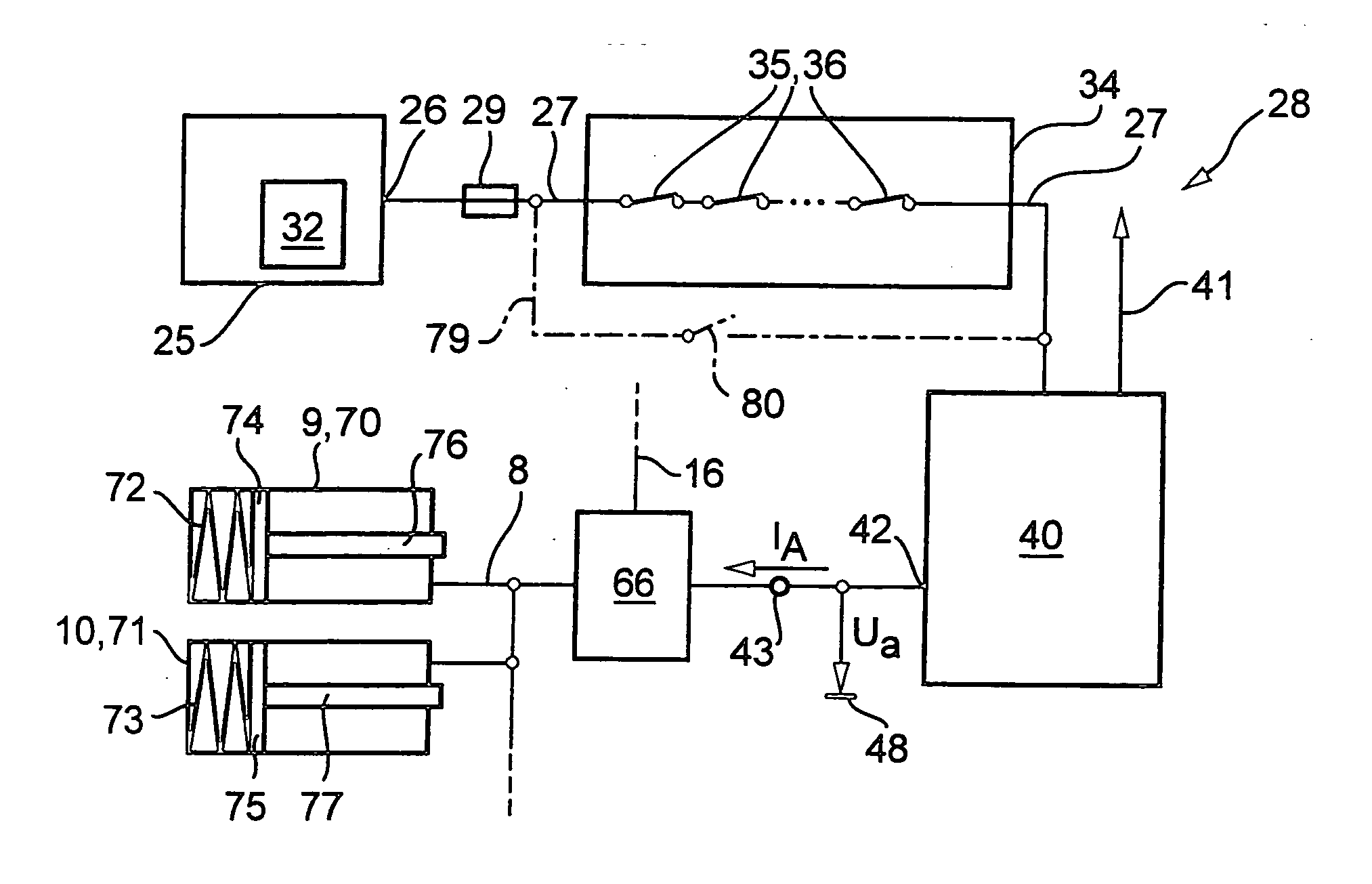
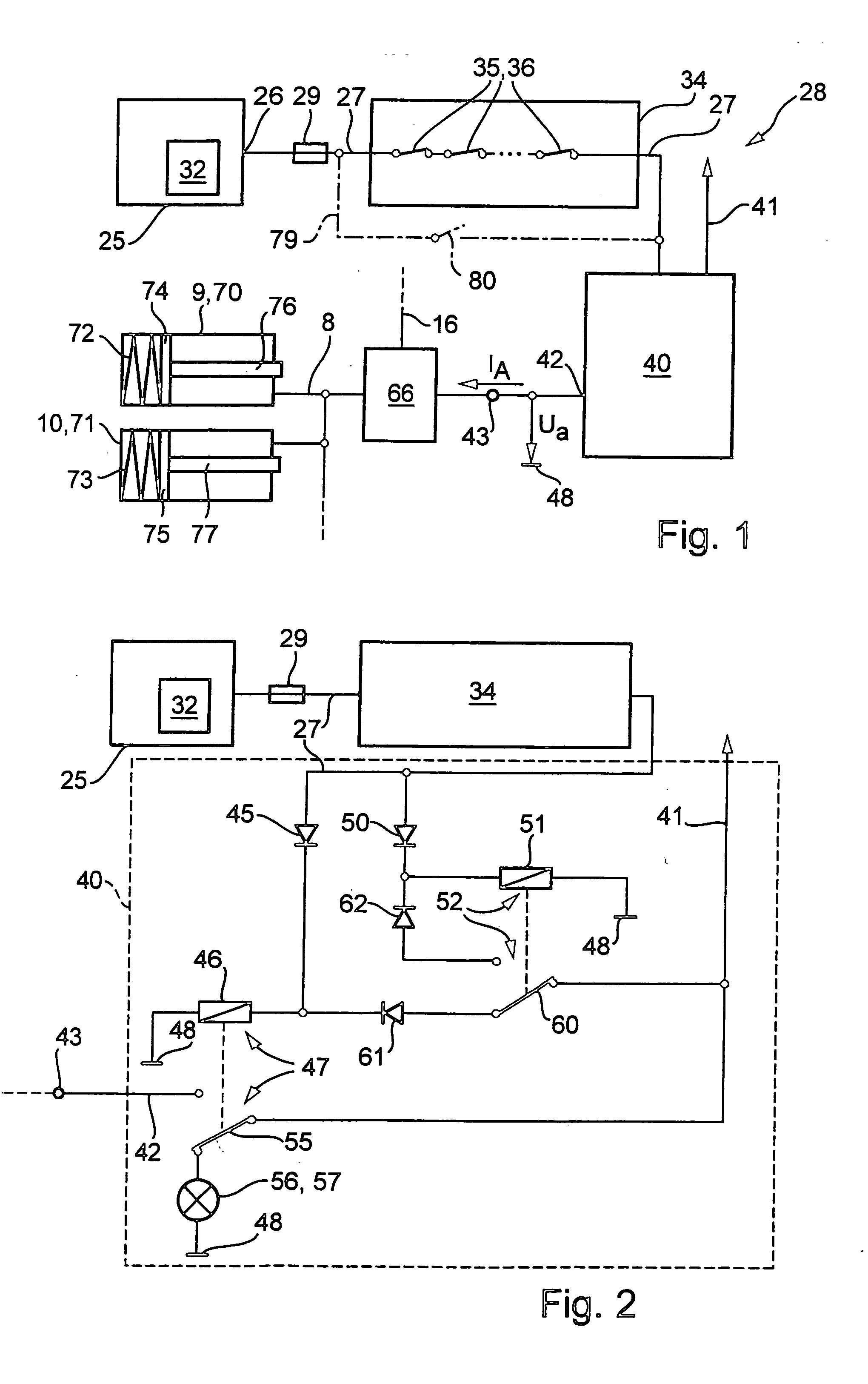
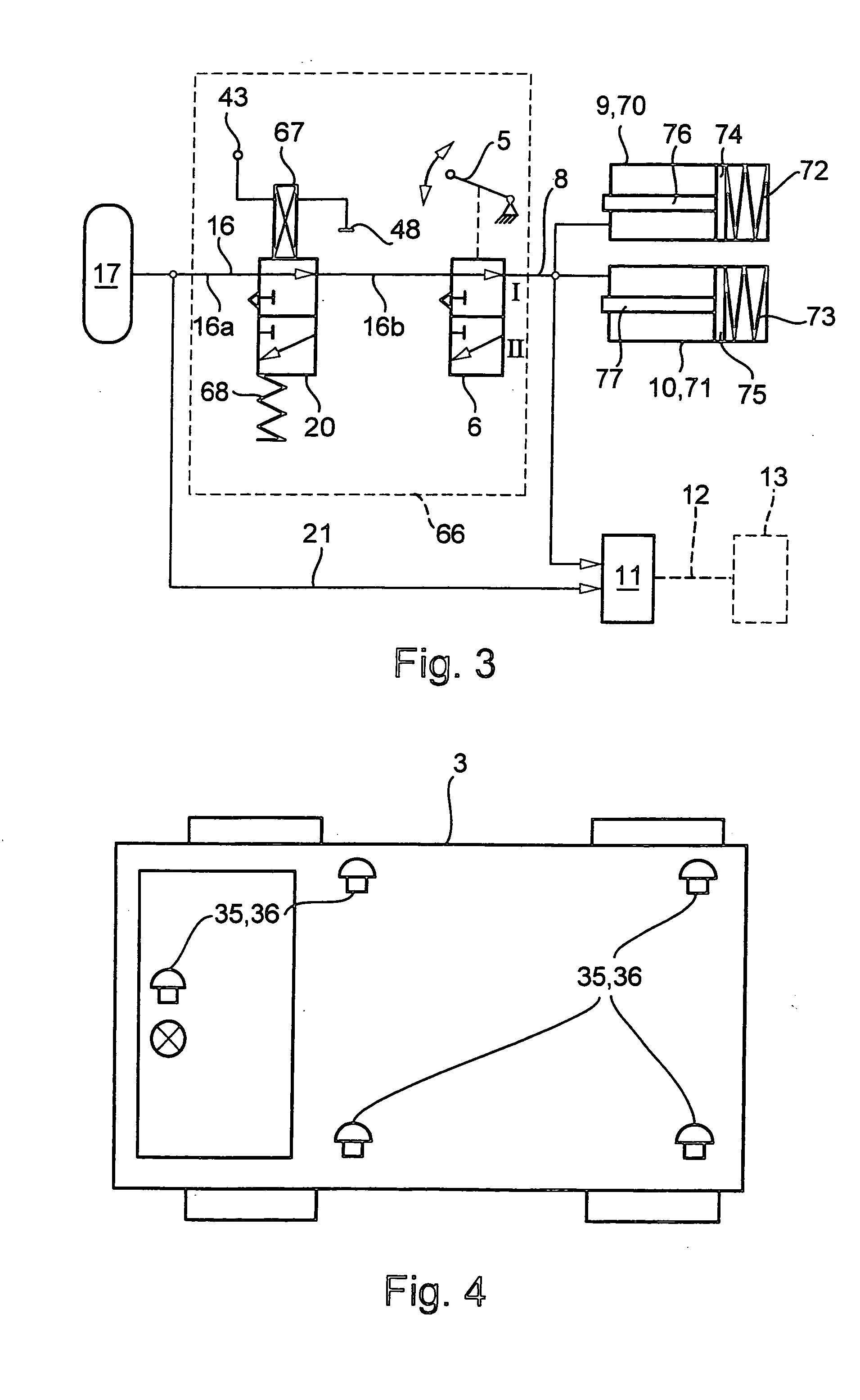
[0134] In contrast to the third exemplary embodiment according to FIG. 7, in the fourth embodiment according to FIG. 9 the second emergency brake switching valve connects, in the nonenergized state of the assigned fourth electromagnet 195, the second reservoir vessel 259, provided for the service brake device, to the actuation line 255. If the fourth electromagnet 195 is energized, it switches over the second emergency brake switching valve 252 into its other switched position, in which case it fluidically connects the actuation line 255 to the second fluid line 250 into which the service brake valve 251 is inserted. The connections to the second emergency brake switching valve 252 are entirely interchanged in FIG. 9 in comparison with the embodiment according to FIG. 7, and thus adapted to the changed actuation of the fourth electromagnet 195.

[0135] In addition, the pneumatic part of the fourth exemplary embodiment of the emergency braking device 28 has, according to FIG. 9, a saf...


PUM


Abstract

A brake system for a vehicle can be operated without a driver. It has a service brake device, a parking brake device and an emergency braking device. At least the wheel brake devices of the wheels of one axle of the vehicle have emergency brake actuators which switchover the assigned wheel brake devices into the braking state as a result of the triggering of an emergency braking operation. The emergency braking operation can be triggered either manually by means of an emergency operator control device or automatically by means of a monitoring device if the latter has detected an unacceptable operating state of the vehicle in the driverless operating mode.

Description

BACKGROUND AND SUMMARY OF THE INVENTION [0001] The invention relates to a brake system for a utility vehicle which can be operated without a driver and which is in particular also provided and approved for operation with a driver. [0002] Such utility vehicles are provided, inter alia, for traffic within an enclosed site, for example works site. They move autonomously between predefined locations, essentially without the intervention of an operator or driver. The vehicle can move, for example, along a permanently predefinable route. Here, situations may occur in which a vehicle which moves without a driver has to be stopped abruptly, for example because an obstacle is unexpectedly situated on the route of the vehicles. [0003] In such vehicles which are operated in a driverless fashion, devices are known which brake the vehicle when there is contact with an obstacle, as is apparent, for example, from DE 42 25 963 A1 or DE 92 16 134 U1. [0004] Nowadays, utility vehicles with approval a...

Claims


Application Information

Patent Timeline
IPC IPC(8): B60T7/12B60T7/20B60T13/66B60T17/18B60T17/22
CPCB60T7/12B60T17/18B60T13/662
Inventor BAUER, WOLF-DIETRICHHAEMMERLING, CARSTENSCHWARZHAUPT, ANDREASSPIEGELBERG, GERNOTSTAHL, WOLFGANG
Owner DAIMLER AG
Why Eureka
Try Eureka