Plasma processing apparatus and method

a processing apparatus and plasma technology, applied in plasma techniques, ion beam tubes, coatings, etc., can solve the problems of irregular plasma, inability to always maintain, and inability to generate and achieve the effect of generating plasma steadily and quickly

Inactive Publication Date: 2005-02-10
CANON KK
View PDF7 Cites 18 Cited by
  • Summary
  • Abstract
  • Description
  • Claims
  • Application Information

AI Technical Summary

Benefits of technology

[0012] Accordingly, in order to solve the prior art problems, it is an exemplary object of the present invention to provide a plasma-processing apparatus and method for generating the plasma steadily and quickly, and for stabilizing and maintaining the once generated plasma until the matching state reaches the matching position.
[0013] A plasma-processing apparatus according to one aspect of the present invention includes a vacuum chamber for accommodating an object to be processed and for providing plasma processing to the object under a vacuum or reduced environment, an impedance matching unit configured for impedance matching, the impedance matching unit being provided between the vacuum chamber and a microwave oscillator for generating microwaves, and a controller for controlling actions of the impedance matching unit based on a relationship among a matching state of the impedance matching unit, a microwave strength distribution necessary to generate plasma for the matching state, and a matching state of the impedance matching unit which minimizes a reflected wave during the plasma processing.
[0014] Thus, the present invention can provide a plasma-processing apparatus and method for generating the plasma steadily and quickly, and for stabilizing and maintaining the once generated plasma until it reaches the matching position.

Problems solved by technology

However, the unit has some problems in that: (1) it cannot generate the plasma steadily and quickly; (2) it cannot always maintain the once generated plasma until the time the matching state is equal to the matching position; and (3) a change from the plasma generation state to the matching position is not always along the most direct route.
These problems result from the facts that the conventional impedance matching unit operates without recognizing: (1) a matching state that can generate the plasma, (2) a matching area that destabilizes or extinguishes the plasma, and (3) a matching position, etc.
As a consequence, there occur some problems: (1) The plasma is not generated if the matching state range that can generate the plasma is narrow, (2) an area that destabilizes or extinguishes the plasma cannot stably maintain the plasma, if this matching area is located between the matching state that can generate the plasma and the matching position for the generated plasma, and (3) insufficiently matched, irregular plasma occurs for a long period of time.
When the plasma is not generated quickly, the microwave radiation electrically damages and disadvantageously heats an object to be processed, preventing the high-quality processing of the object.
For example, when the object is a semiconductor device, the radiated microwaves destroy the structure in the semiconductor device and deteriorate its characteristics.
In addition, the unstable plasma and the long period of time to reach the matching position cause the irregular plasma to generate and damage the object.
In particular, when the object is a semiconductor device, contacts of the irregular plasma with the object destroy the structure in the semiconductor device and deteriorate its characteristics because of the high energy (potential) of the irregular plasma.
Moreover, before the matching state reaches the matching position after the plasma is generated, it passes through a matching state that makes the plasma unstable.
The matching state requires a long period of time to reach the matching position due to the unstable plasma or it will become an unstable state called hunting.
The unstable plasma damages the object as discussed above, and applies an excessive load to the plasma-processing apparatus, thereby causing damage and breakdown of the apparatus.

Method used


Image

  • Plasma processing apparatus and method
  • Plasma processing apparatus and method
  • Plasma processing apparatus and method

Examples


first embodiment

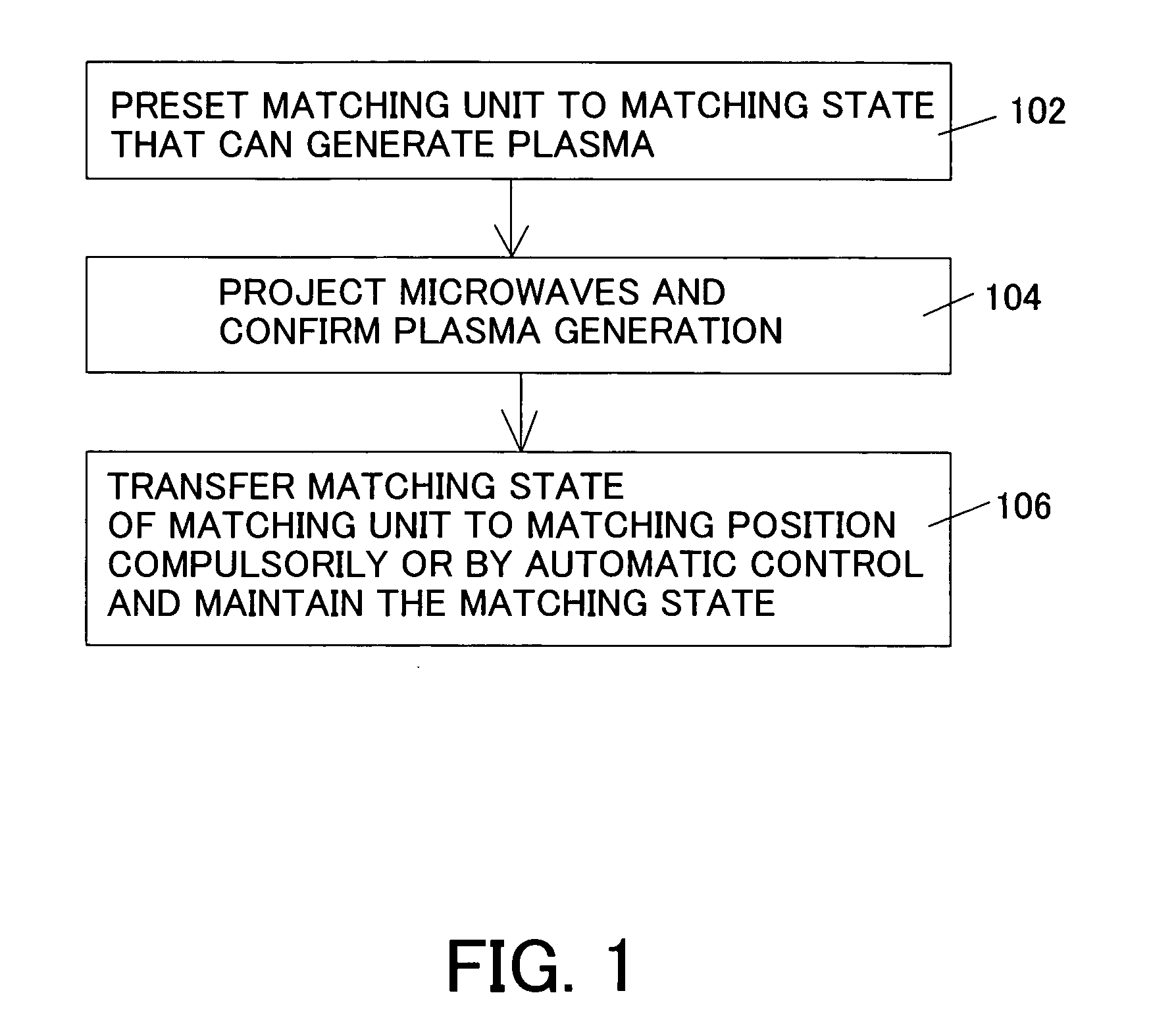
[0023] First Embodiment

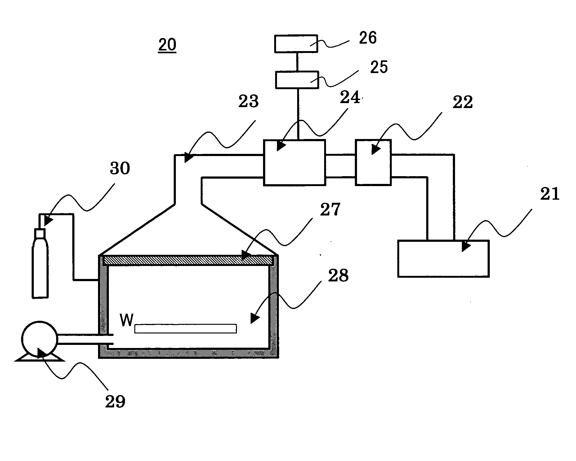
[0024] A description will now be given of a plasma-processing apparatus and method according to a first embodiment according to the present invention, with reference to the accompanying drawings. FIG. 6 shows a schematic block diagram of a structure of an inventive plasma-processing apparatus 20. The plasma-processing apparatus 20 includes a microwave oscillator 21, an isolator 22, a microwave waveguide 23, an impedance matching unit 24, a controller 25, a memory 26, a separation means 27, a vacuum chamber 28, a vacuum exhaust means 29, and a gas supply means 30.

[0025] The microwave oscillator 21 includes, for example, a magnetron, and generates microwaves, for example, of 2.45 GHz. The microwaves are then converted by a mode converter into a TM, TE or TEM mode or the like, before propagating through the microwave waveguide 23. The isolator 22 prevents microwaves reflected on the waveguide etc. from returning to the microwave oscillator 21 by absorbing the re...

second embodiment

[0045] Second Embodiment

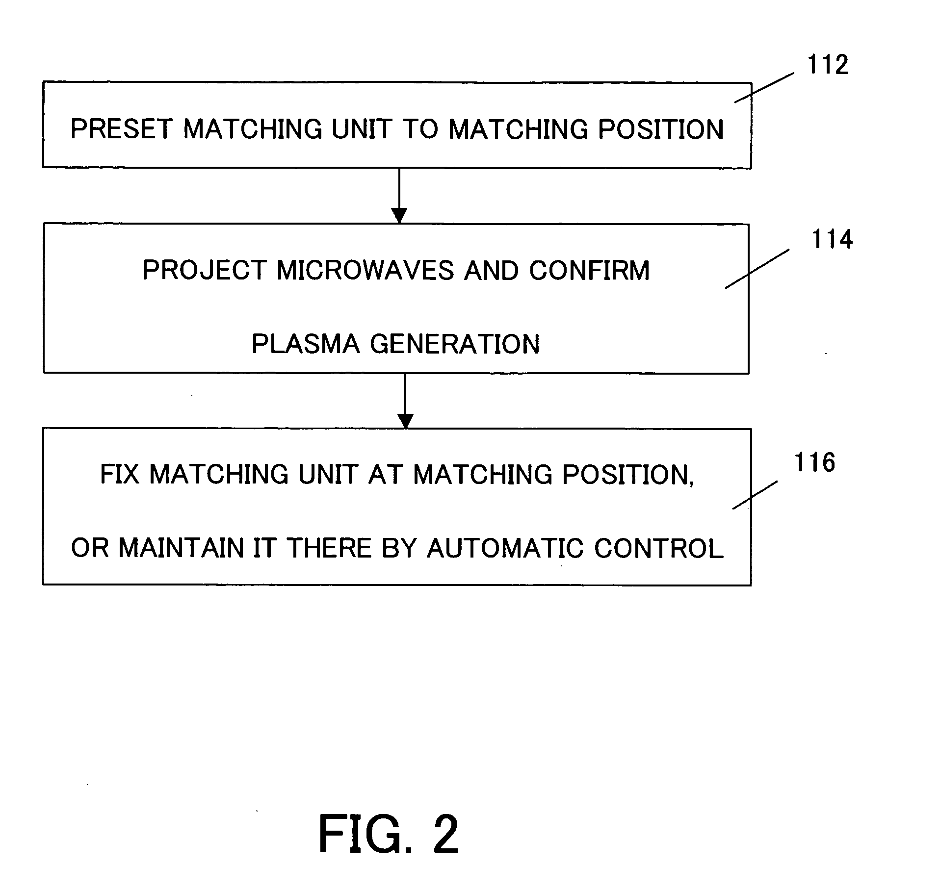
[0046] When the apparatus featured as shown in FIG. 7 uses the microwaves at an output of 3 kW for plasma processing, the controller 25 presets the impedance matching unit 24 to a matching state in an area that can generate the plasma at 3 kW as shown by a broken line in FIG. 7, thereby steadily generating the plasma similar to the first embodiment. On the other hand, especially in FIG. 7, when the matching position c32 for 3 kW is included in the area that can generate the plasma at 3 kW, the plasma is generated more steadily and becomes stable. In other words, the plasma becomes steady as soon as it is generated, by presetting the impedance matching unit to the matching position c32, and reduces damage to the object by irregular plasma that may occur during the transfer to the matching position. FIG. 2 shows this control flow.

[0047] Referring to FIG. 2, the distribution shown in FIG. 7 and the matching position c32 for 3 kW are measured and stored in the m...

third embodiment

[0049] Third Embodiment

[0050] Alternatively, the controller 25 may generate the plasma at an output lower than the microwave's output used for the processing, maintain the good matching state of the impedance matching unit 24, enhance the originally desired microwave's output, and conduct the plasma processing. In other words, this embodiment stabilizes the plasma using the manipulations shown in FIG. 1 by controlling the microwave oscillator 21 while the impedance matching unit 24 is set to the matching state that can generate the plasma at an output (for example, 1 kW) lower than the microwave's output (for example, 3 kW) used for the processing, and starts plasma processing by projecting the microwaves of 1 kW. Then, the plasma processing may follow by increasing the microwaves up to 3 kW while the impedance matching unit 24 keeps minimizing the reflected waves. This system can reduce the direct irradiations of microwaves upon the object before the plasma is generated. This is ac...


PUM

PropertyMeasurementUnit
reflection coefficientaaaaaaaaaa
impedanceaaaaaaaaaa
microwave strengthaaaaaaaaaa

Abstract

A plasma-processing apparatus includes a vacuum chamber for accommodating an object to be processed and for providing plasma processing to the object under a vacuum or reduced environment, an impedance matching unit configured for impedance matching, the impedance matching unit being provided between the vacuum chamber and a microwave oscillator for generating microwaves, and a controller for controlling actions of the impedance matching unit based on a relationship among a matching state of the impedance matching unit, a microwave strength distribution necessary to generate plasma for the matching state, and a matching state of the impedance matching unit which minimizes a reflected wave during the plasma processing.

Description

[0001] This application claims a foreign priority benefit based on Japanese Patent Application No. 2003-288255, filed on Aug. 6, 2003, which is hereby incorporated by reference herein in its entirety as if fully set forth herein. BACKGROUND OF THE INVENTION [0002] The present invention relates generally to plasma processing with microwave-generated plasma, and more particularly a method and apparatus for generating and stabilizing the plasma. [0003] The recent developments of electronic apparatuses have caused increasing demand for manufacturing of high-quality electronic components contained in these electronic apparatuses. To manufacture certain electronic components, such as semiconductor devices, a microwave plasma-processing apparatus is needed for certain processing steps such as coating, etching, and ashing. [0004] The microwave plasma-processing apparatus typically introduces the microwaves from a microwave oscillator into a vacuum chamber or a plasma-processing chamber so a...

Claims


Application Information

Patent Timeline
Patent Type & Authority Applications(United States)
IPC IPC(8): H05H1/46C23C16/511C23F4/00H01J7/24H01J27/16H01J37/08H01J37/32H01L21/00H01L21/3065H01L21/31H05H1/00
CPCH01J37/32192H05H1/46H01J37/32256
Inventor YOKOSHIMA, SHIGENOBUTAKAMURA, YUICHI
Owner CANON KK
Why Eureka
Try Eureka