Control apparatus for brushless DC motor
a control apparatus and dc motor technology, applied in the direction of motor/generator/converter stopper, electronic commutator, dynamo-electric converter control, etc., can solve the problem of increasing the sine component of the induced voltage proportional to dc motor causes more errors, and the angular velocity of the rotor is often significantly different, so as to improve the estimation accuracy
- Summary
- Abstract
- Description
- Claims
- Application Information
AI Technical Summary
Benefits of technology
Problems solved by technology
Method used
Image
Examples
first embodiment
Now, a control apparatus for a brushless DC motor according to the invention will be described with reference to the accompanying drawings.
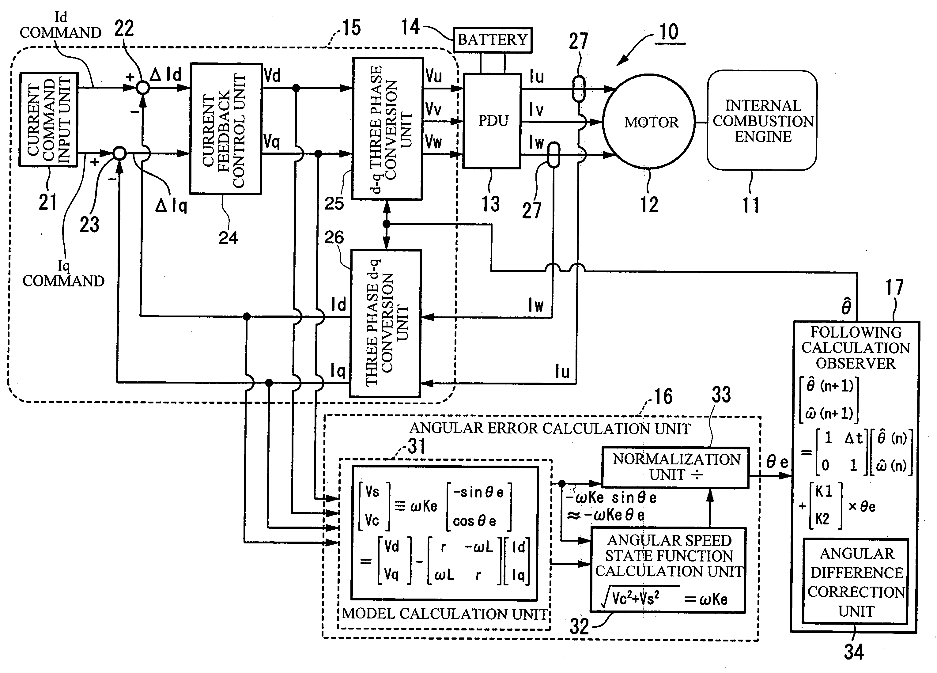
The control apparatus for a brushless DC motor 10 (hereinafter simply referred to as the motor control apparatus 10) according to the first embodiment drives and controls a brushless DC motor 12 (hereinafter simply referred to as the motor 12) included in, for example, a hybrid vehicle as a drive source together with an internal combustion engine 11. The motor 12 includes a rotor (not shown) connected in series to the internal combustion engine 11 and having a permanent magnet used as a field, and a stator (not shown) that generates a rotating magnetic field for rotating the rotor.
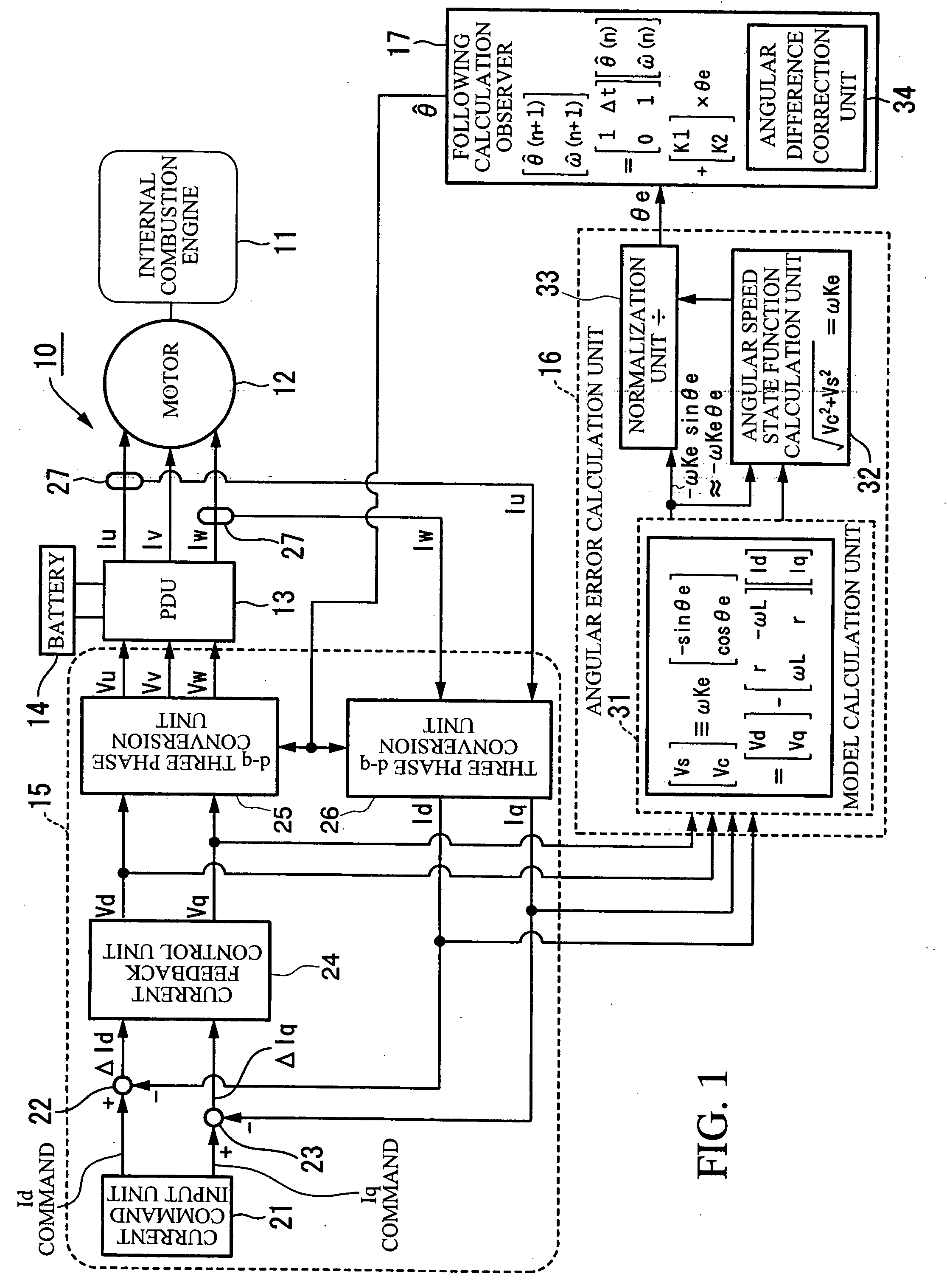
The motor control apparatus 10 includes, as shown in FIG. 1, a power drive unit (PDU) 13, a battery 14, a control unit 15, an angular error calculation unit 16, and an observer 17.
In the motor control apparatus 10, a drive and a regenerative operation of the motor ...
second embodiment
Now, a control apparatus for a brushless DC motor according to the invention will be described with reference to the accompanying drawings.
The control apparatus for a brushless DC motor 40 (hereinafter simply referred to as the motor control apparatus 40) according to the second embodiment includes, as shown in FIG. 10, a power drive unit (PDU) 13, a battery 14, a control unit 15, an observer 17, an angular error calculation unit 41, and a control angle correction unit 42.
The same parts as in the first embodiment are denoted by the same reference numerals, and descriptions thereof will be simplified or omitted.
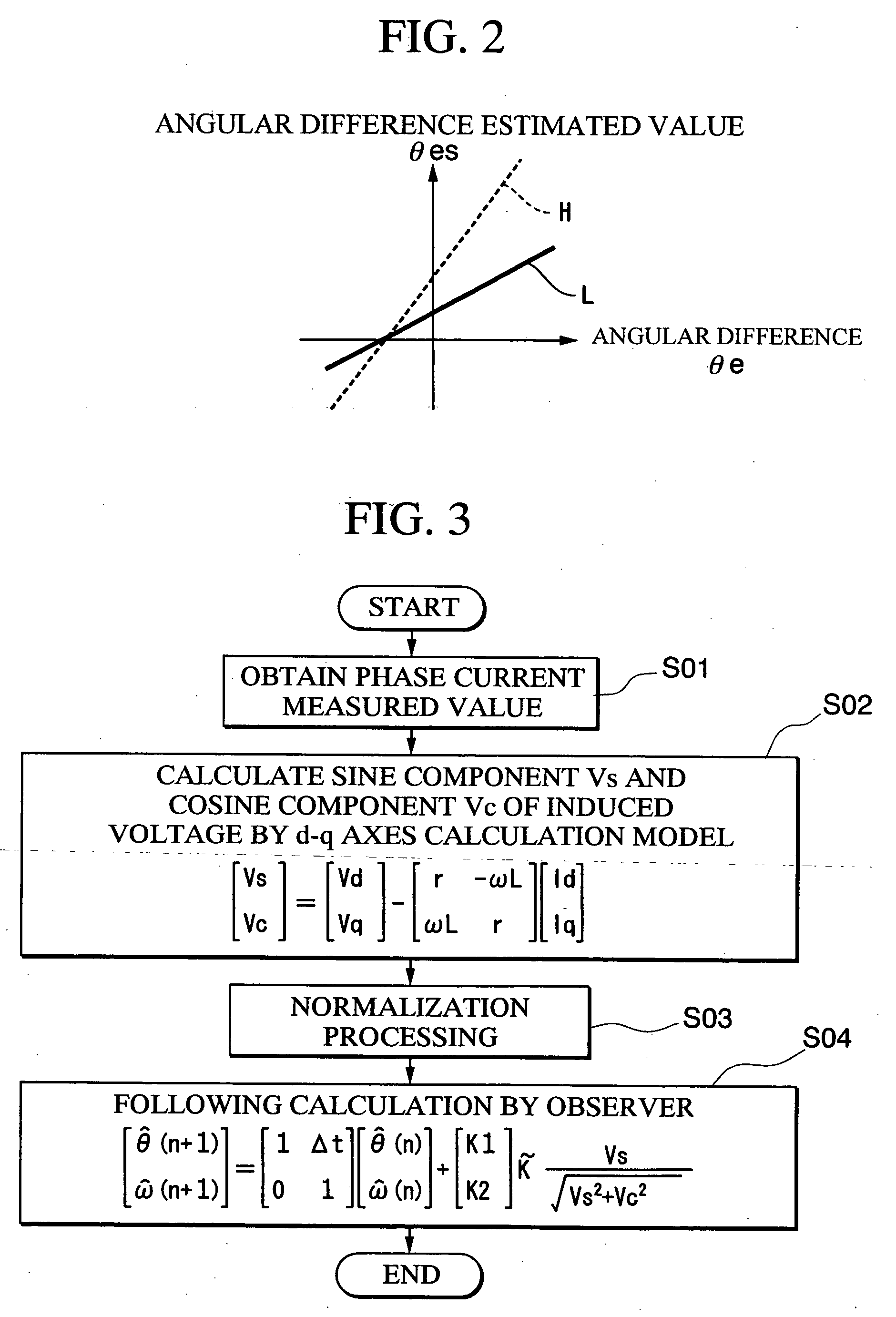
The angular error calculation unit 41 uses the fact that an angular difference θe can be approximated by a sine value sin θe (θe≈sin θe) when an angular difference θe (=θ−θ{circumflex over ( )}) between an estimated rotation angle Δ{circumflex over ( )} with respect to a rotation angle of a rotor and an actual rotation angle θ is relatively small to calculate the angular ...
PUM
 Abstract
Description
Claims
Application Information
 - R&D
- Intellectual Property
- Life Sciences
- Materials
- Tech Scout
- Unparalleled Data Quality
- Higher Quality Content
- 60% Fewer Hallucinations
Browse by: Latest US Patents, China's latest patents, Technical Efficacy Thesaurus, Application Domain, Technology Topic, Popular Technical Reports.
© 2025 PatSnap. All rights reserved.Legal|Privacy policy|Modern Slavery Act Transparency Statement|Sitemap|About US| Contact US: help@patsnap.com


