Motor temperature sensor system and method to determine motor performance

a temperature sensor and motor technology, applied in the direction of motor/generator/converter stopper, dynamo-electric converter control, instruments, etc., can solve problems such as degradation of motor performan

Inactive Publication Date: 2005-02-10
KENDRO LAB PRODS
View PDF13 Cites 26 Cited by
  • Summary
  • Abstract
  • Description
  • Claims
  • Application Information

AI Technical Summary

Problems solved by technology

It is well known that the magnetic flux density of magnetic materials (i.e., rotor magn

Method used


Image

  • Motor temperature sensor system and method to determine motor performance
  • Motor temperature sensor system and method to determine motor performance
  • Motor temperature sensor system and method to determine motor performance

Examples


Embodiment Construction

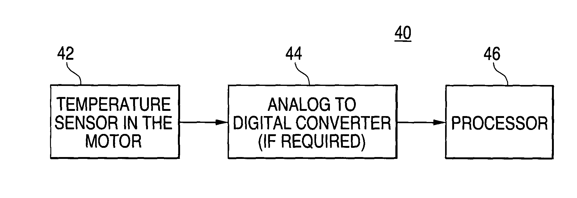
In some preferred embodiments, the invention provides a system and method that determines electrical motor performance using at least one sensed internal temperature of the motor. Preferably, the temperature of one or more rotor magnets is sensed. Preferred embodiments of the invention will now be described with reference to the drawing figures in which like reference numbers refer to like elements throughout.

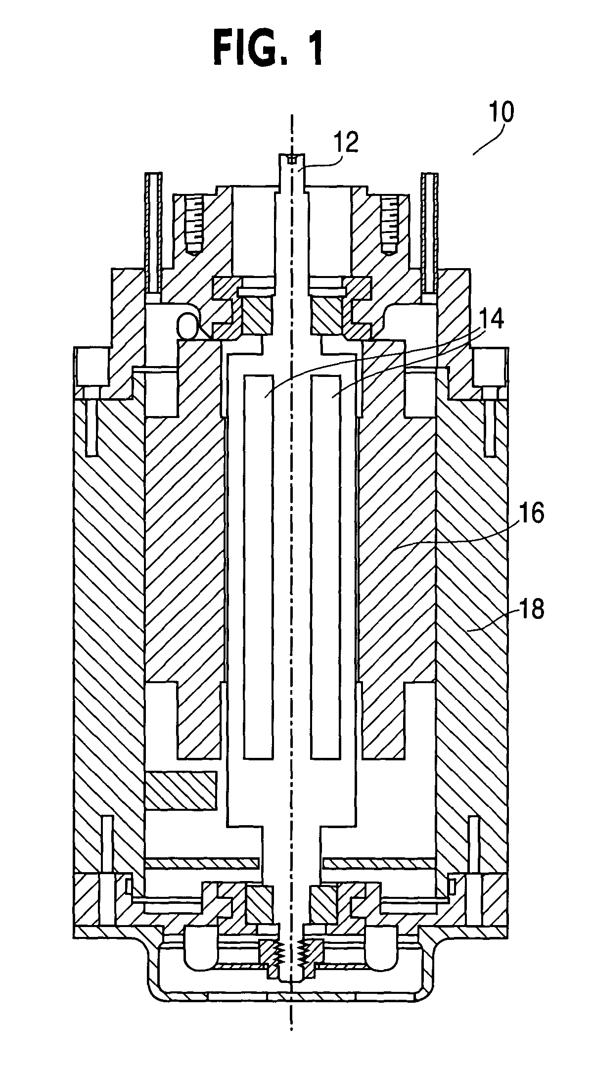
FIG. 1. is a cross-sectional view of a conventional brushless DC motor 10 having a rotor 12, rotor magnets 14, a stator 16, and a motor housing 18. An output mechanical torque is produced on the rotor 12 as a result of the interaction of the magnetic flux of the rotor magnets 14 and the rotating magnetic flux induced by the stator current. These components of brushless DC motors are well known in the art, and therefore for the purposes of this discussion is not further discussed herein.

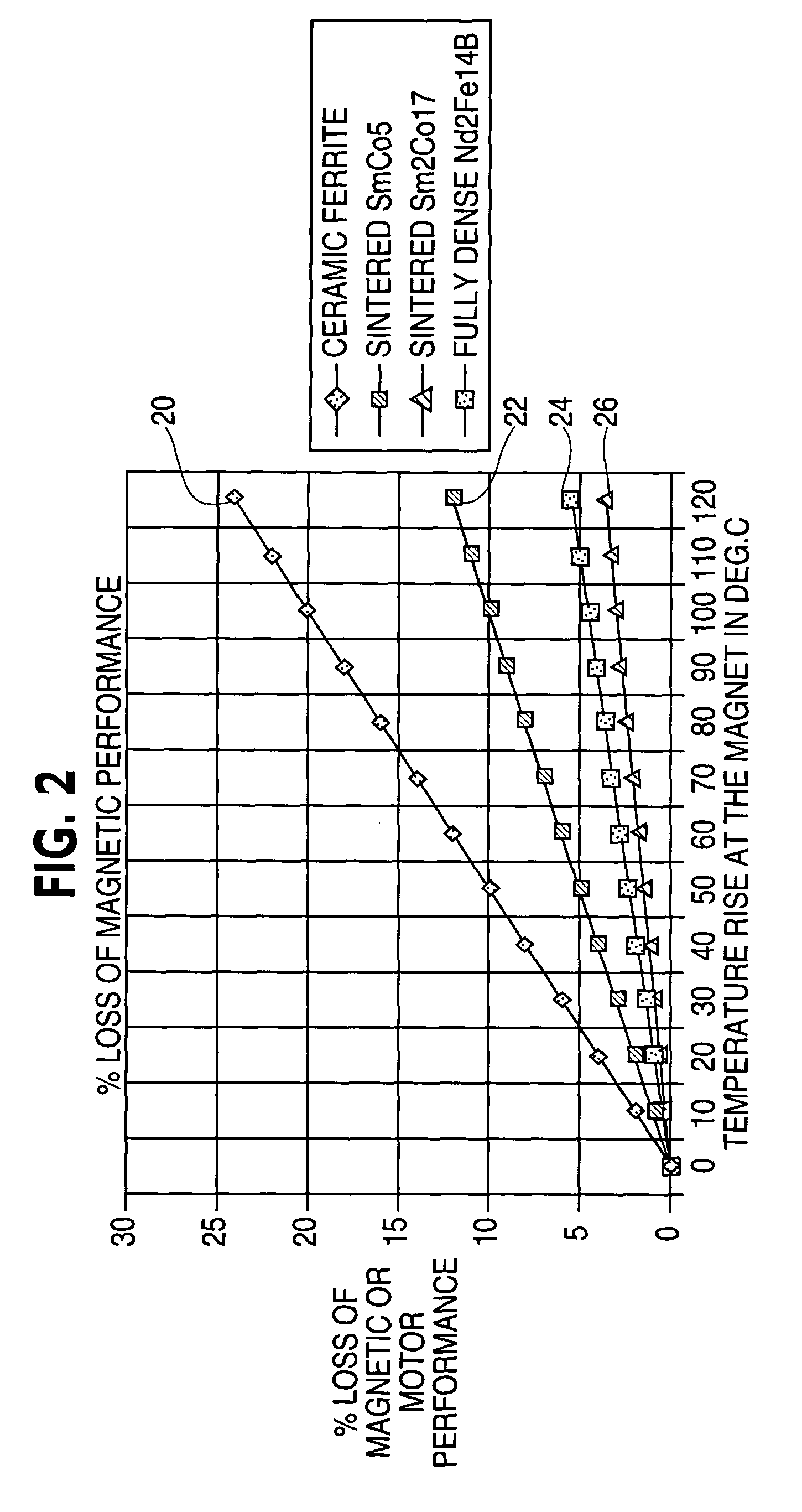
Typically employed magnetic materials experience a decrease in flux density as the temper...


PUM


Abstract

Systems and methods for sensing the temperature of the rotor magnets of an electric motor are provided to facilitate the determination of motor performance characteristics such as the torque of the rotor.

Description

FIELD OF THE INVENTION The present invention relates generally to the field of electric motors. More particularly, the present invention relates to determining electric motor performance using a sensed internal temperature of the motor. BACKGROUND OF THE INVENTION Conventional brushless direct current (DC) motors rely on the magnetic flux created by permanent magnets located on the rotor interacting with magnetic fields from the stator to generate a mechanical torque. Indeed, the output mechanical torque generated by a brushless DC motor is directly proportional to the magnetic flux density of the rotor magnets. Often, performance characteristics of a brushless DC motor are evaluated based on the output mechanical torque generated by the motor as a function of the input stator current. In many applications, it is critical to accurately determine the output mechanical torque produced by a motor for a known stator current. The magnetic flux of the rotor magnets and its relationship...

Claims


Application Information

Patent Timeline
IPC IPC(8): G01K7/42G01K13/08G05D23/00H02K11/00H02P7/00
CPCG01K7/42Y10S388/934H02K11/0047G01K13/08H02K11/25
Inventor CARSON, DAVID M.HALL, RICHARD
Owner KENDRO LAB PRODS
Why Eureka
Try Eureka