Unlock instant, AI-driven research and patent intelligence for your innovation.
Reference voltage generator circuit
Inactive Publication Date: 2005-02-10
NEC ELECTRONICS CORP
View PDF7 Cites 28 Cited by
Summary
Abstract
Description
Claims
Application Information
AI Technical Summary
This helps you quickly interpret patents by identifying the three key elements:
Problems solved by technology
Method used
Benefits of technology
Benefits of technology
The above and other objects, features and advantages of the present invention will become more fully understood from the detailed description given her
Problems solved by technology
The number of elements is thereby large to undesirably increase a circuit area and current consumption.
Method used
Image
Click on the blue label to locate the original text in one second.
Reading with bidirectional positioning of images and text.
Examples
first embodiment
The first embodiment is now explained with specific numerical values.
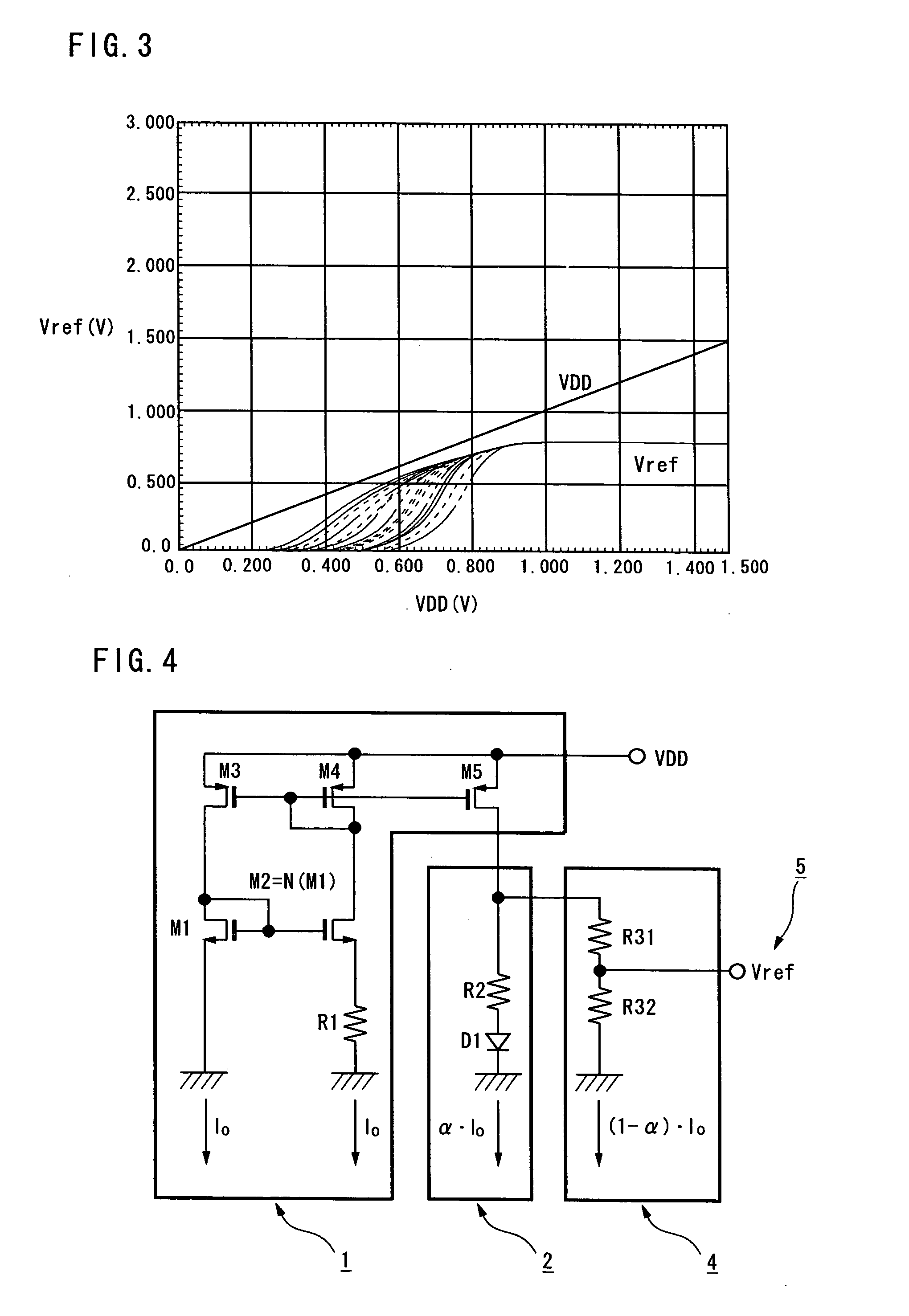
Setting values in this embodiment are as follows: The ratio of the resistors are: R1, R2=12R1, R3=1.7R1, The ratio N of the transistors M1 and M2 is: N=11, The forward voltage and temperature characteristics of the diode D1 are:
A reference voltage Vref with respect to a power voltage under the above conditions is calculated. As indicated in FIG. 3, the reference voltage Vref=0.8V and ΔVref / ΔT=0 when the power voltage is 0.9V and above.
In the first embodiment, the first and second current-voltage converter circuits 2 and 3 are connected in parallel to the drain ...
second embodiment
The second embodiment divides the resistor of the second current-voltage converter circuit. By setting the connection between the divided resistors as the reference voltage output terminal, it is possible to obtain a still lower reference voltage than the reference voltage obtained in the first embodiment.
FIG. 6 is a circuit diagram showing a third embodiment of the invention. FIG. 7 is a graph showing the time to generate a reference voltage. The first and second embodiments require several msec to generate a reference voltage after power-on. The third embodiment allows reducing the elapsed time to generate a reference voltage.
The circuit of the third embodiment has a startup circuit 6 in addition to the circuit shown in FIG. 4. The other elements in FIG. 6 are the same as those in FIG. 4, and the same elements are denoted by the same reference symbols and redundant description is omitted.
The startup circuit 6 has a NMOS transistor M6 and PMOS transistors M7 and M8. The gate of...
PUM
Abstract
A reference voltage generator circuit for generating a reference voltage and outputting the voltage from an output terminal comprises a constant current source circuit having a current mirror circuit, for outputting a reference voltage; and first and second current-voltage converter circuits connected in parallel to an output of the constant current source circuit, wherein the second current-voltage generator circuit outputs a reference voltage lower than a bandgap voltage.
Description
BACKGROUND OF INVENTION 1. Field of Invention The present invention relates to reference voltage generator circuits and, particularly, to a reference voltage generator circuit with less power voltage dependency and temperature dependency. 2. Description of Related Art A bandgap reference voltage generator circuit is known as a reference voltage generator circuit with less power voltage dependency and temperature dependency. In the bandgap reference voltage generator circuit, an output reference voltage is fixed to about 1.25V, which is a bandgap voltage. Recently, low-voltage semiconductor devices have been developed. Conventional bandgap reference voltage generator circuits are incapable of generating a reference voltage of less than 1.25V. Japanese Unexamined Patent Application Publication No. 11-045125 proposes a low-level reference voltage generator circuit. It introduces an improved structure of the bandgap reference voltage generator circuit. FIG. 8 shows a basic structur...
Claims
Application Information
Patent Timeline
Application Date:The date an application was filed.
Publication Date:The date a patent or application was officially published.
First Publication Date:The earliest publication date of a patent with the same application number.
Issue Date:Publication date of the patent grant document.
PCT Entry Date:The Entry date of PCT National Phase.
Estimated Expiry Date:The statutory expiry date of a patent right according to the Patent Law, and it is the longest term of protection that the patent right can achieve without the termination of the patent right due to other reasons(Term extension factor has been taken into account ).
Invalid Date:Actual expiry date is based on effective date or publication date of legal transaction data of invalid patent.

