Image processing apparatus

a technology of image processing and processing apparatus, which is applied in the direction of digital output to print units, instruments, television systems, etc., can solve the problems of inability to equally handle the data used in the copying and scanning process, the inability to display, management, and the use of input images from the same device. , to achieve the effect of enhancing user-friendliness and low cos

Inactive Publication Date: 2005-02-10
KK TOSHIBA +1
View PDF5 Cites 18 Cited by
  • Summary
  • Abstract
  • Description
  • Claims
  • Application Information

AI Technical Summary

Benefits of technology

[0007] The object of the present invention is to provide an image processing apparatus capable of realizing necessary compression techniques for MFPs at low cost, as well as enhancing user-friendliness.

Problems solved by technology

If different compression techniques are applied to the respective processes, the cost rises due to provision of a plurality of compression means and the productivity lowers due to mutual conversion of compressed data.
The difference in compression technique results in such a problem that the data used in the copying and scanning processes, which use input images from the same device, cannot equally be handled for display, management, etc.
Furthermore, as regards the MFP configuration, it is difficult to increase the system extensibility at low cost, by connecting not only units for color scan and color print or units for black-and-white scan and black-and-white print, but also units for color scan and black-and-white print, or the like, wherein the number of signals in devices is different.

Method used


Image

  • Image processing apparatus
  • Image processing apparatus
  • Image processing apparatus

Examples


first embodiment

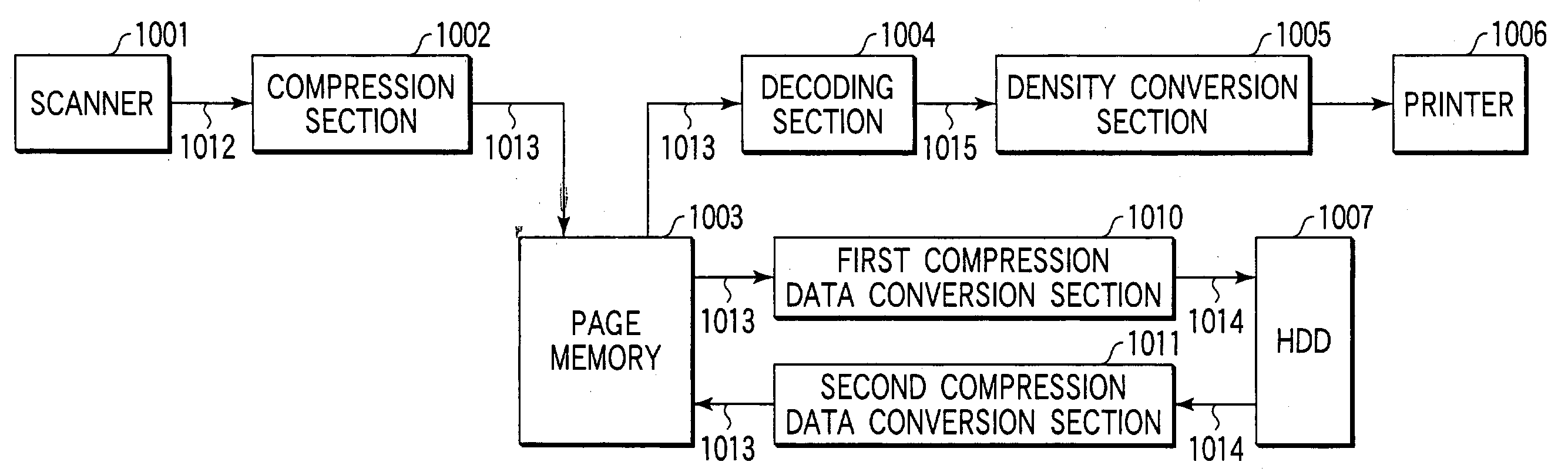
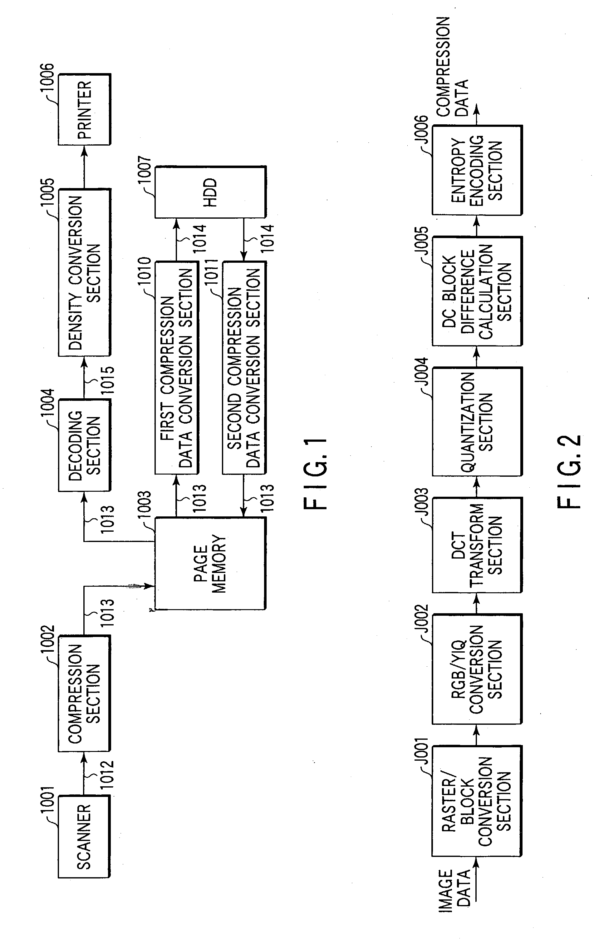
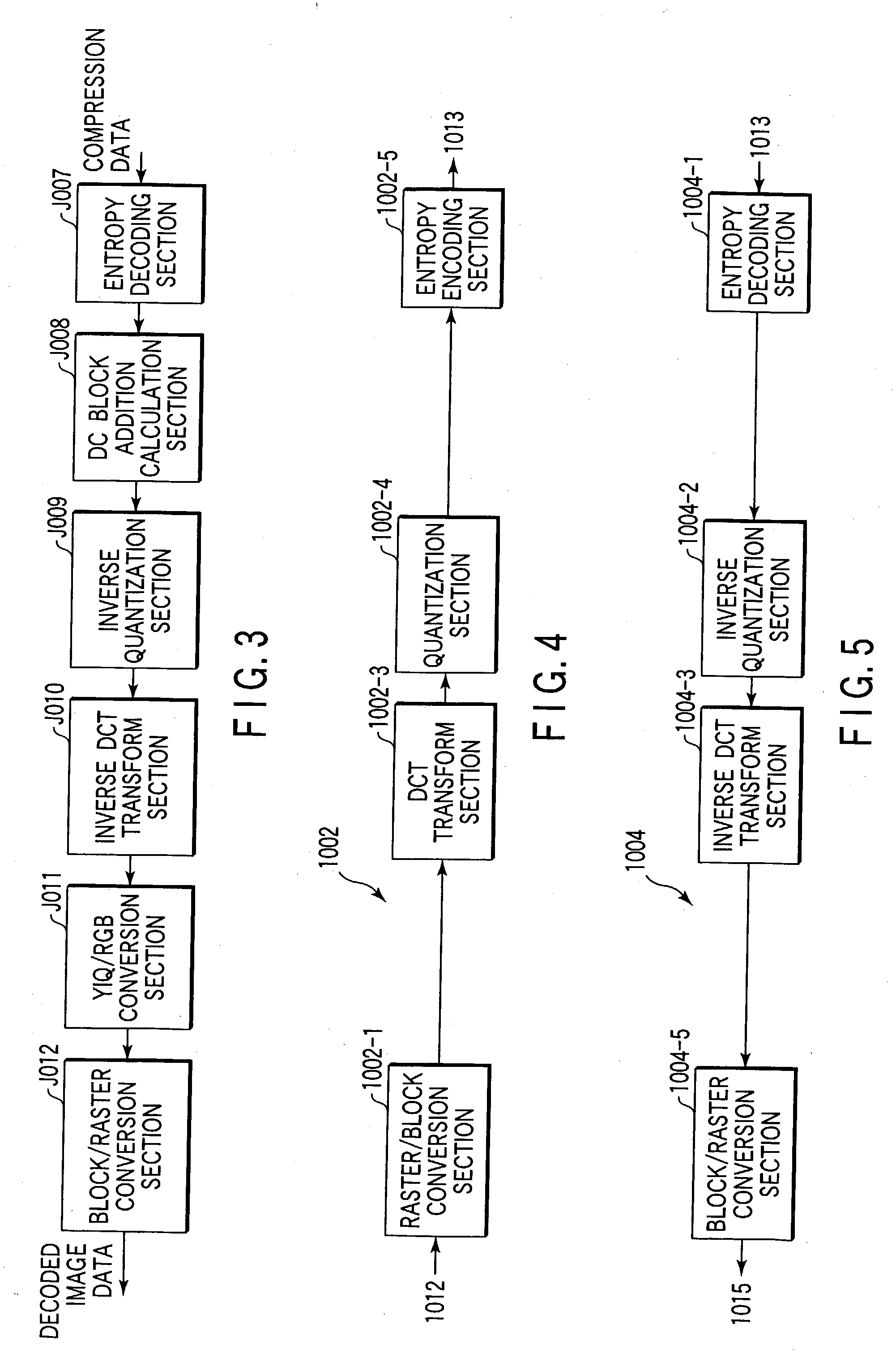
[0047]FIG. 1 schematically shows the structure of an MFP according to an image processing apparatus of the present invention. The MFP comprises a scanner 1001 that inputs a black-and-white image signal 1012; a compression section 1002 that compresses the black-and-white image signal to first compression data; a page memory 1003 that stores the first compression data 1013; a decoding section 1004 that decodes the first compression data 1013 to a black-and-white image signal 1015; a density conversion section 1005 that converts the black-and-white image signal 1015 to a density signal; a printer 1006 that prints out the density signal; a first compression data conversion section 1010 that converts the first compression data 1013 stored in the page memory to second compression data 1014; a second compression data conversion section 1011 that converts the second compression data 1014 to the first compression data 1013; and a hard disk drive (HDD) 1007 that stores the second compression ...

second embodiment

[0135] the present invention will now be described.

[0136] An MFP according to the second embodiment is provided with a JPEG viewer (not shown) in addition to the structure of the first embodiment shown in FIG. 1. The JPEG viewer may be an ordinary one, and it interprets header information and displays a JPEG-compressed image.

[0137] The second embodiment is the same as the first embodiment except for a compression section 2002, a decoding section 2004, a first compression data conversion section 2010, a second compression data conversion section 2011, and generated first and second compression data 2013, 2014.

[0138] The compression section 2002 has the same structure as the compression section 1002 of the first embodiment shown in FIG. 4. The structure of the compression section 2002 is not shown since it is the same as the first embodiment. The compression section 2002 comprises a raster / block conversion section 2002-1, a DCT transform section 2002-3, a quantization section 2002-4...

third embodiment

[0164] the present invention will now be described.

[0165]FIG. 22 schematically shows the structure of an MFP according to the third embodiment. The MFP comprises a scanner 3001, a compression section 3002, a page memory 3003, a decoding section 3004, a density conversion section 3005, a printer 3006, a first compression data conversion section 3010, a second compression data conversion section 3011, a hard disk drive (HDD) 3007 and a JPEG viewer 3012.

[0166] The third embodiment is the same as the second embodiment except for the color scanner 3001 that inputs a color image 3013, the compression section 3002 that compresses the color image, first color compression data 3014 capable of being rotated, etc., second color compression data 3015 capable of being viewed through the JPEG viewer 3012, the first compression data conversion section 3010 and second compression data conversion section 3011 that can mutually convert the first and second compression data, and the decoding section ...


PUM


Abstract

Without repeating compression/decompression operations, an editing process such as rotation can be executed using first compression data, and second compression data, whose compression ratio is increased, can be stored in a hard disk drive.

Description

BACKGROUND OF THE INVENTION [0001] The present invention relates to an image processing apparatus that performs an image process for an input color image, for example, in a digital color copying machine that reads a color image on an original and forms a copy image thereof. [0002] Conventionally, copying machines with a single function of copying have been predominant. However, with recent development of digital technology, MFPs (Multi-Function Peripherals) with multiple functions, such as a copying function, a scanning function and a printing function, have increasingly been manufactured and marketed. [0003] A method disclosed in Jpn. Pat. Appln. KOKAI Publication No. 11-69164 is a senior invention of the inventor of the present invention, which relates to a digital color copying machine. In the senior invention, an image is fixed-length compressed in units of a block, thereby realizing an editing function such as a rotational process function at low cost. In addition, the fixed-le...

Claims


Application Information

Patent Timeline
Patent Type & Authority Applications(United States)
IPC IPC(8): H04N7/30G06T9/00H04N1/41H04N1/413
CPCH04N1/41G06T9/007
Inventor TABATA, SUNAOKANNO, HIROKI
Owner KK TOSHIBA
Why Eureka
Try Eureka