Head centering jig for femoral resurfacing

a femoral resurfacing and centering jig technology, applied in the field of head centering jig, can solve the problems of loose design and loosening of artificial joints, and achieve the effects of accurate positioning, convenient alignment of guide members, and accurate positioning

Active Publication Date: 2005-02-10
CORIN
View PDF10 Cites 33 Cited by
  • Summary
  • Abstract
  • Description
  • Claims
  • Application Information

AI Technical Summary

Benefits of technology

[0027] Advantageously, the guide member may comprise a hollow tube and the axis defined by the guide member may comprise a central axis of the tube. This provides for accurate positioning of the drill required to drill the long pin into the femoral head. Alternatively, the guide member may comprise a channel member. This provides the advantage of not having to disassemble the jig prior to its removal once the long pin has been drilled into the femoral head.
[0038] Advantageously, the kit may comprise a plurality of jigs, each jig being as previously described and differing from each other in terms of the dimensions of the means for at least partially receiving the femoral neck and / or the predetermined distance from said means at which the axis defined by the guide member intersects the plane defined by the first member. This provides the advantage of enabling the kit to accommodate the range of femur sizes present in the population.

Problems solved by technology

During the 1950's and early 1960's, a number of surgeons developed hip implants using this type of bearing, although many of these designs had a tendency to work loose early on as the techniques used to anchor them to the bone were not very successful.
This plastic debris causes an irritation.
Furthermore, as the particles get between the bone and the artificial joint, this irritation causes surrounding bone to be absorbed by the body, leading to a loosening of the artificial joint.
There are, however, a number of problems with the prior art head centering jig shown in FIG. 3.
Another problem with the prior art head centering jig 30 is that it is bulky since the arm 44 must extend from the lateral positioning pin 28 at the mid-lateral femoral cortex to the femoral head 36 while still allowing the stylus 58 to rotate about the guide tube 38.

Method used


Image

  • Head centering jig for femoral resurfacing
  • Head centering jig for femoral resurfacing
  • Head centering jig for femoral resurfacing

Examples


first embodiment

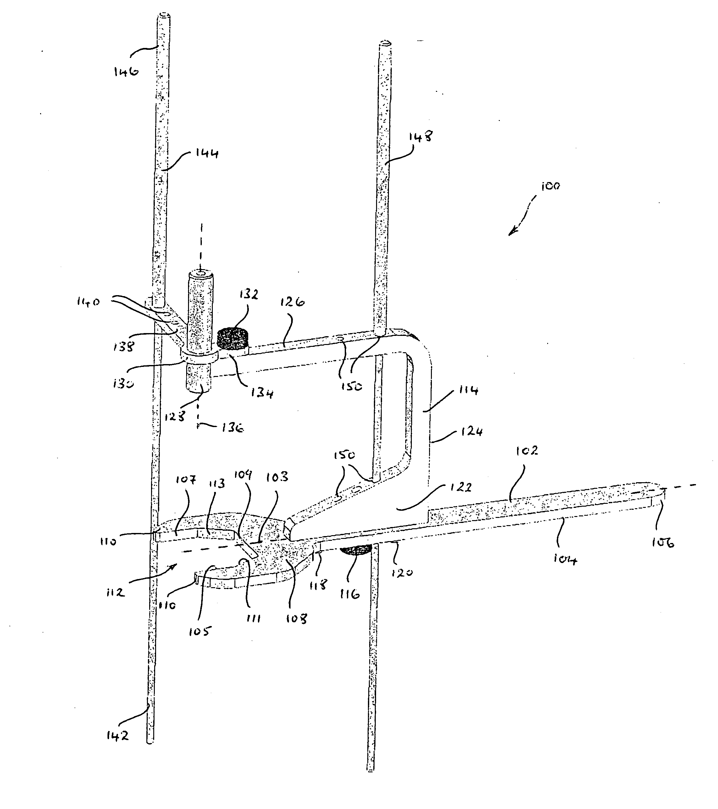
[0081] Thereafter, as with the head centering jig of the first embodiment, the plane defined by the locating tool 202 is tilted by raising and lowering the handle 204 until such time as the first alignment rod 114 is aligned parallel to the central axis of the femoral neck when viewed anteriorly. Assuming that the appropriately sized jig has been selected and that the femoral neck is a close fit within the closed circle defined by arcuate surfaces 210 and 218, the central axis 136 of the guide tube 128 will lie within a plane parallel to the coronal plane. By then aligning the first alignment rod 144, the central axis 136 is brought into coincidence with the central axis of the femoral neck. If additional alignment is required a second alignment rod 148 may be aligned with the central axis of the femoral neck when viewed laterally. Once the surgeon is satisfied that the central axis 136 of the guide tube 128 is aligned with the central axis of the femoral neck he may use his free ha...

second embodiment

[0090] The locating tool 302 is moveable between an open position, as shown in FIG. 21, and a closed position, as shown in FIG. 19. In the open position the first and second arcuate members 308a and 308b are sufficiently spaced apart to permit the receipt of the femoral neck. Once the locating tool 302 is in position it is closed and held in the closed position by the retaining member 114 which is mounted on the elongate handle 304. The locating tool 302 can be additionally held in a closed position by the provision of a suitable closure means (not shown) at an end of the first and second arcuate members 308a and 308b remote from the first and second elongate handles 342 and 372. Alternatively the locating tool 302 may be provided with arcuate members similar to the arcuate members 208 and 216 described in relation to the

[0091] As with the head centering jig of the first and second embodiments, in order to accommodate the range of femur sizes present in the population, it will be ne...


PUM


Abstract

There is described a jig for identifying a point on the femoral head which is in alignment with a central axis of the femoral neck. The jig comprises a first member which defines a plane and has means for at least partially receiving the femoral neck. The jig also comprises a guide member which is mounted apart from the first member and which defines an axis at right angles to the plane defined by the first member. The axis of the guide member intersects the plane at a point which is a predetermined distance away from the means receiving the femoral neck. In addition, the jig comprises an elongate alignment means which is mounted with respect to the first member and which is spaced apart from, but extends parallel to, the axis of the guide member. There is also described a kit for use in the resurfacing of the femoral head. The kit comprises at least one jig as previously described.

Description

FIELD OF THE INVENTION [0001] The present invention relates to a head centering jig for use in the preparation of the femur in hip resurfacing procedures and to a kit comprising such a jig. BACKGROUND OF TEE INVENTION [0002] Conventional Total Hip Replacement (THR) is a very successful procedure for the treatment of arthritis of the hip, a condition which causes considerable pain and loss of movement. As is well known, the hip is a ball and socket joint which allows the upper leg to move from side to side, back to front, and to rotate. The joint is made up of the head of the femur (the ball) which fits into the acetabulum (the socket). In a healthy hip, both the head of the femur and the acetabulum are covered with cartilage which provides a smooth surface allowing the joint to move freely. [0003] The earliest Total Hip Replacement (THR) procedure, in 1938, involved an implant in which both surfaces were made from metal and was known as a metal-on-metal bearing. During the 1950's an...

Claims


Application Information

Patent Timeline
Patent Type & Authority Applications(United States)
IPC IPC(8): A61B17/17A61F2/30A61F2/32A61F2/34A61F2/36A61F2/46
CPCA61B17/175A61F2/32A61F2/34A61F2/36A61F2002/4681A61F2/4607A61F2002/30878A61F2002/3611A61F2002/365A61F2/3601
Inventor NEVELOS, JAMESKRIKLER, STEVENSTACHNIW, MYRON B.BISHAY, MICHAEL
Owner CORIN
Why Eureka
Try Eureka