Method and apparatus for measuring characteristics of core-annular flow

a technology of characteristics and flow, applied in the direction of pressure difference measurement between multiple valves, instruments, digital computer details, etc., can solve the problems of inability to achieve accurate and reliable measurements of caf. , to achieve the effect of improving the accuracy of caf measurement, the effect of increasing the number of steps

Active Publication Date: 2005-02-10
CIDRA
View PDF87 Cites 44 Cited by
  • Summary
  • Abstract
  • Description
  • Claims
  • Application Information

AI Technical Summary

Benefits of technology

The foregoing and other objects, features and advantages of the present invention will become more apparent in light of the following detailed description of exemplary embodiments thereof.

Problems solved by technology

The challenge in transporting bitumen through pipelines is derived from its high static viscosity, on the order of 105 times that of water at standard conditions.
If bitumen froth behaved as a Newtonian fluid, i.e. the shear stress was strictly proportional to shear rate, pumping bitumen froth would require several orders of magnitude more power than that required to pump water, rendering pipeline transfer impractical.
Historically, obtaining accurate and reliable measurements of CAF has proven technically difficult and economically challenging.
Firstly, CAF flows may be extremely abrasive.
The presence of ˜10% by volume of non-conductive bitumen further complicates the flow measurement, as does the possibility of the pipe containing up to several percent of entrained air by volume.
Mechanical wear of these meters results in high maintenance, calibration, and replacement costs, providing an incentive for operators to evaluate alternative measurement technologies.
In addition, these meters are invasive.
As a result, installation or maintenance of the meter often requires at least a portion of the flow process to be isolated.
While the use of NMRI was shown to be successful in characterizing velocity, the use of NMRI equipment may be economically challenging for many applications.

Method used


Image

  • Method and apparatus for measuring characteristics of core-annular flow
  • Method and apparatus for measuring characteristics of core-annular flow
  • Method and apparatus for measuring characteristics of core-annular flow

Examples


examples

FIG. 5 depicts a test loop 50 for the flow of bitumen froth used in testing a flow meter of the present invention. The test loop 50 includes a main loop 52 of 10 inch, schedule 10 pipe coupled to the inlet and outlet of a 300 horsepower screw pump 54. The length of the main loop 52 is approximately 100 meters. Branching from the main loop 50 proximate the inlet of the pump 54 are two bypass legs 56 and 58. Bypass leg 56 is formed from 4 inch, schedule 10 pipe and bypass leg 58 is formed from 6 inch schedule 160 pipe. The test loop 50 was filled with bitumen froth, and the pump 54 was operated to pump the bitumen froth through the test loop 50.

A series of tests was performed by attaching a flow meter embodying the present invention at various locations (locations #1 and #2) throughout the test loop 50. The flow rate of the bitumen froth was adjusted by adjusting the speed of the pump 54. The various tests are described hereinafter.

In a first test, the flow meter embodying the pre...


PUM

PropertyMeasurementUnit
flow velocityaaaaaaaaaa
pressureaaaaaaaaaa
flow velocityaaaaaaaaaa

Abstract

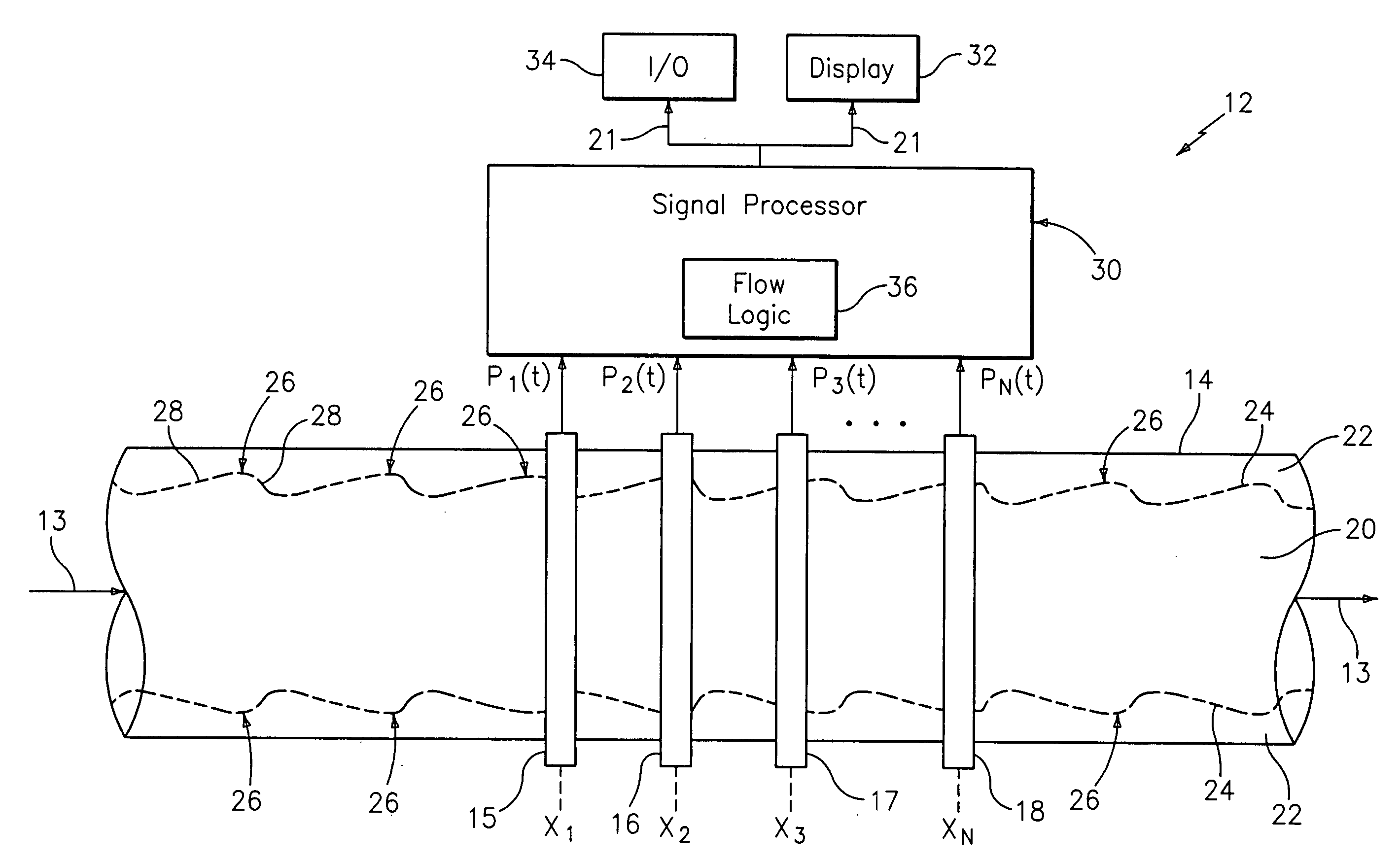
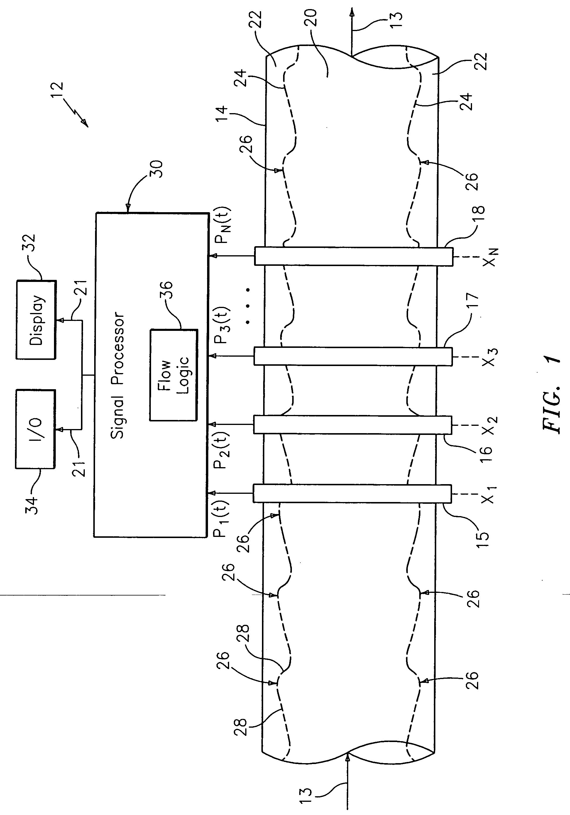
An apparatus and method are disclosed wherein at least one parameter associated with a core-annular flow (CAF) in a pipe is measured by sensing unsteady pressures associated with undulations formed at the interface of a core region and an annular region in the CAF at different axial locations along the pipe. The at least one parameter, which may include a flow velocity of the CAF, Mach number associated with the CAF, and a volumetric flow rate of the CAF, is determined using sensed unsteady pressures. The CAF may be developed from a shear thinning fluid, such as bitumen froth or from a wood pulp fiber suspension. Alternatively, the CAF may be developed from a lubricating fluid, such as water, and a fluid to be transported, such as oil, where the fluid to be transported forms the core region and the lubricating fluid forms the annular region.

Description

TECHNICAL FIELD This invention relates to a method and apparatus for measuring at least one parameter associated with a core-annular flow within a pipe, and more particularly to a method and apparatus for measuring at least one parameter such as flow velocity and / or volumetric flow rate associated with a core-annular flow within a pipe using array processing techniques. BACKGROUND Core-annular flow (CAF) through a pipe is characterized by a fluid or mixture disposed at the center or core of the flow, known as the core region, and a relatively low viscosity fluid or mixture disposed about the core region between the core region and the walls of the pipe, known as the annular region. A phenomenon associated with CAF is that the lower viscosity annular region naturally migrates to the high sheer region found at the wall of the pipe where it acts to levitate the core region off of the pipe wall and lubricate the flow. One example of CAF is found in the oilsands processing industry, w...

Claims


Application Information

Patent Timeline
Patent Type & Authority Applications(United States)
IPC IPC(8): G01F1/34G01F1/704G01F1/712G01F1/74G01L7/00
CPCG01F1/74G01F1/34
Inventor GYSLING, DANIEL L.
Owner CIDRA
Why Eureka
Try Eureka