Multiprocessor system with interactive synchronization of local clocks

a multi-processor system and clock technology, applied in multiplex communication, generating/distributing signals, instruments, etc., can solve the problems of imposing significant variability in latencies, imposing longer latencies, and affecting the validity of time stamps across processors, so as to achieve a small latency in obtaining

Active Publication Date: 2005-02-10
HEWLETT-PACKARD ENTERPRISE DEV LP +1
View PDF17 Cites 45 Cited by
  • Summary
  • Abstract
  • Description
  • Claims
  • Application Information

AI Technical Summary

Benefits of technology

[0014] A major advantage of the invention is that it provides for on-going synchronization of asynchronously-driven processor clocks. Applications with multiple threads running concurrently on different processors can be assured that the time stamps they obtained were actually obtained in the order indicated by the time stamps. Application time stamps are available locally at all times, so there is little latency in obtaining the application time stamps. There is no common-clock signal source that might serve as a single point of system failure. Since the method can be implemented on a hardware level, no software interruptions or redesigns are required. These and other features and advantages are apparent from the description below with reference to the following drawings.

Problems solved by technology

The external data paths not only impose longer latencies, but also impose significant variability in latencies—e.g., as bus or network contentions are resolved.
If the different threads are subject to long and variable latencies, the time stamps may not be validly comparable across processors.
As a result, operations can be mis-ordered upon reconstruction.
However, failure of the clock-signal source causes failure of all the counters, which undermines fault tolerance otherwise provided by an SMP system.
Also, as the multi-processor system scales, it can be difficult to transmit a single extremely high-frequency clock signal to a large number of components distributed across multi-processor integrated circuits and / or circuit boards.
The accuracy of the resulting corrections can be limited as the loads and stores required by the synchronization software are subject to the same unpredictable latencies suffered by all such transactions.
If the software is run “on demand” when the main application requires a time stamp, the time stamps will be subject to inaccuracies due to the long and unpredictable latencies involved.
If the clock-calibration software is run in the background, it will consume computational power, incurring a significant performance penalty for the main applications.

Method used


Image

  • Multiprocessor system with interactive synchronization of local clocks
  • Multiprocessor system with interactive synchronization of local clocks
  • Multiprocessor system with interactive synchronization of local clocks

Examples


Embodiment Construction

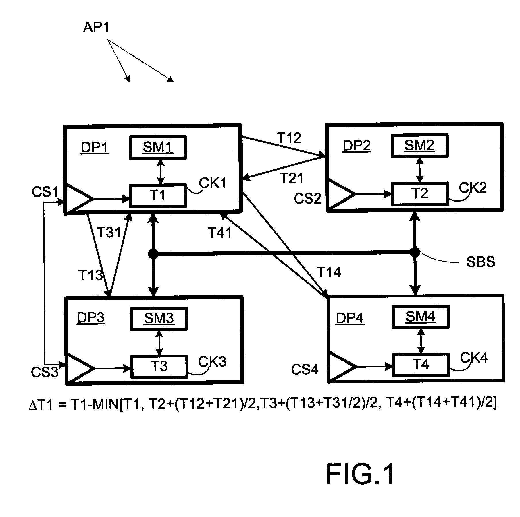
[0017] A computer system AP1 comprises multiple data processors DP1-DP4, as shown in FIG. 1. Each processor DP1-DP4 has a respective clock CK1-CK4, which is a counter driven by a respective clock signal CS1-CS4. At each instant, each clock CK1-CK4 indicates a respective time T1-T4. Clock signals CS1 and CS3 have a common source so clocks CK1 and CK3 operate synchronously, but clock signals CS2 and CS4 are generated independently (of each other and of CS1 and CS3), as so synchronization is required. Each processor DP1-DP4 has a respective synchronization manager SM1-SM4 for managing synchronization operations across processors. Processors DP1-DP4 communicate over system bus SBS.

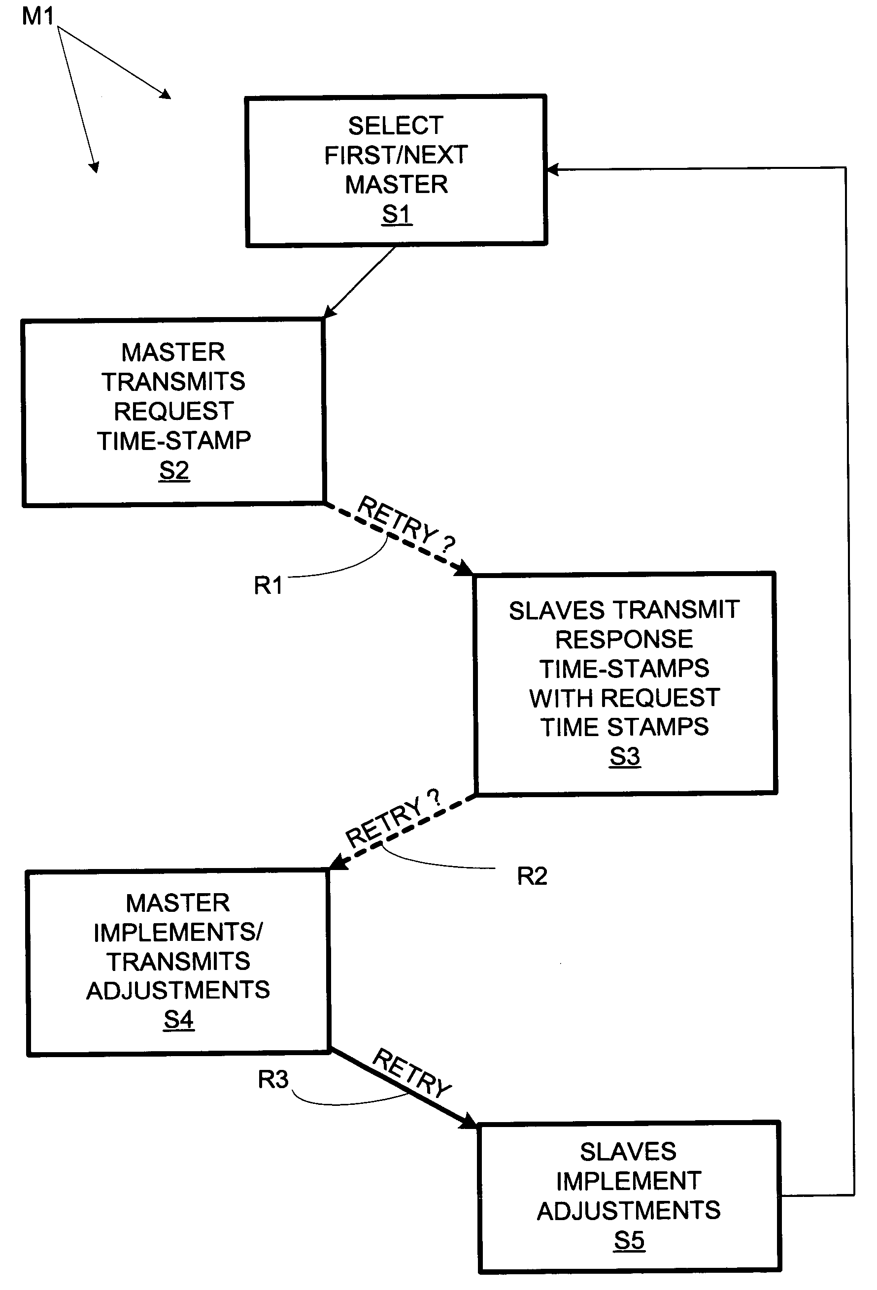
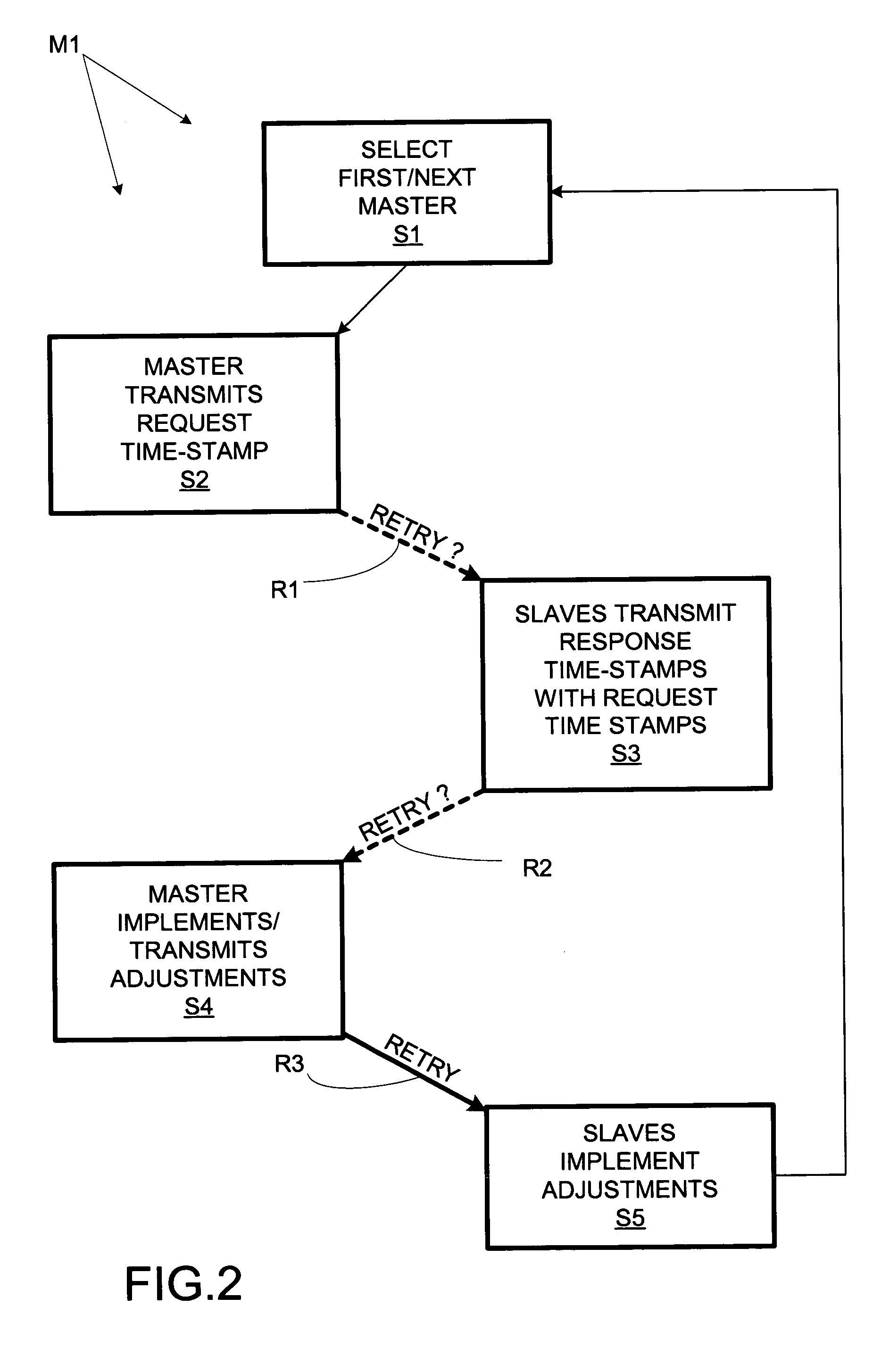
[0018] Synchronization managers SM1-SM4 provide for implementation of a method Ml, flow-charted in FIG. 2, of the invention. At step S1, a first synchronization master is selected from processors DP1-DP4. In the illustrated embodiment, each processor is assigned a schedule for assuming master status. In this ...


PUM


Abstract

A multiprocessor computer system comprises multiple data processors, each with an internal clock for providing time stamps to application software. The processors take turns as synchronization masters. The present master transmits a “request” time stamp (indicating the time of transmission according to the local clock) to the other (“slave”) processors. Each slave processor responds by returning a “response” time stamp (indicating the time of transmission of the response according to the local slave clock) of its own along with the received request time stamp. The master calculates clock adjustment values from the time of receipt of the responses and the included time stamps. This allows asynchronous clocks to be synchronized so that application time stamps can be validly compared across processors.

Description

BACKGROUND OF THE INVENTION [0001] The present invention relates to computer systems and, more particularly, to clock synchronization in multiprocessor systems. A major objective of the invention is to provide an approach to clock synchronization scaleable to multi-processor systems with large numbers of processors. [0002] Some computer applications, e.g., some database applications, time stamp certain operations. In principle, time stamping operations allows a sequence of such operations to be reconstructed, e.g., in the event of a software fault or system crash. However, the time stamps must be sufficiently accurate and precise to allow the sequence to be reconstructed properly. [0003] High-precision time stamps have been provided using local clocks, which are typically free-running counters; the counters are typically driven by fixed-frequency system clock signals so that the counters count at a fixed rate. By locating it “near” a processor, a clock can be quickly accessed by sof...

Claims


Application Information

Patent Timeline
Patent Type & Authority Applications(United States)
IPC IPC(8): G06F1/12G06F1/14G06F9/00H04J3/06
CPCH04J3/0638G06F1/14G06F1/12
Inventor MORRIS, DALE C.ROSS, JONATHAN K.
Owner HEWLETT-PACKARD ENTERPRISE DEV LP
Why Eureka
Try Eureka