Electronic control pedal position sensing device assembly method

a technology of electronic control and pedal position, applied in the direction of mechanical control devices, process and machine control, instruments, etc., to achieve the effect of accurate representation of pedal position, convenient and effective calibration and adjustment, and reliable yet inexpensive pedal position

Inactive Publication Date: 2005-02-17
STAKER WILLIAM C
View PDF57 Cites 13 Cited by
  • Summary
  • Abstract
  • Description
  • Claims
  • Application Information

AI Technical Summary

Benefits of technology

[0006] In view of the foregoing background, it is therefore an object of the present invention to provide a pedal operable with an electronic throttle controller that can be easily and effectively calibrated and adjusted during assembly of the pedal. It is further an object of the present invention to provide a reliable yet inexpensive pedal position sensor that accurately represents pedal position.

Problems solved by technology

Therefore, any errors in reference angles represent a significant portion of the total sensor output.

Method used


Image

  • Electronic control pedal position sensing device assembly method
  • Electronic control pedal position sensing device assembly method
  • Electronic control pedal position sensing device assembly method

Examples


Embodiment Construction

[0022] The present invention will now be described more fully hereinafter with reference to the accompanying drawings, in which preferred embodiments of the invention are shown. This invention may, however, be embodied in many different forms and should not be construed as limited to the embodiments set forth herein. Rather, these embodiments are provided so that this disclosure will be thorough and complete, and will fully convey the scope of the invention to those skilled in the art. Like numbers refer to like elements throughout.

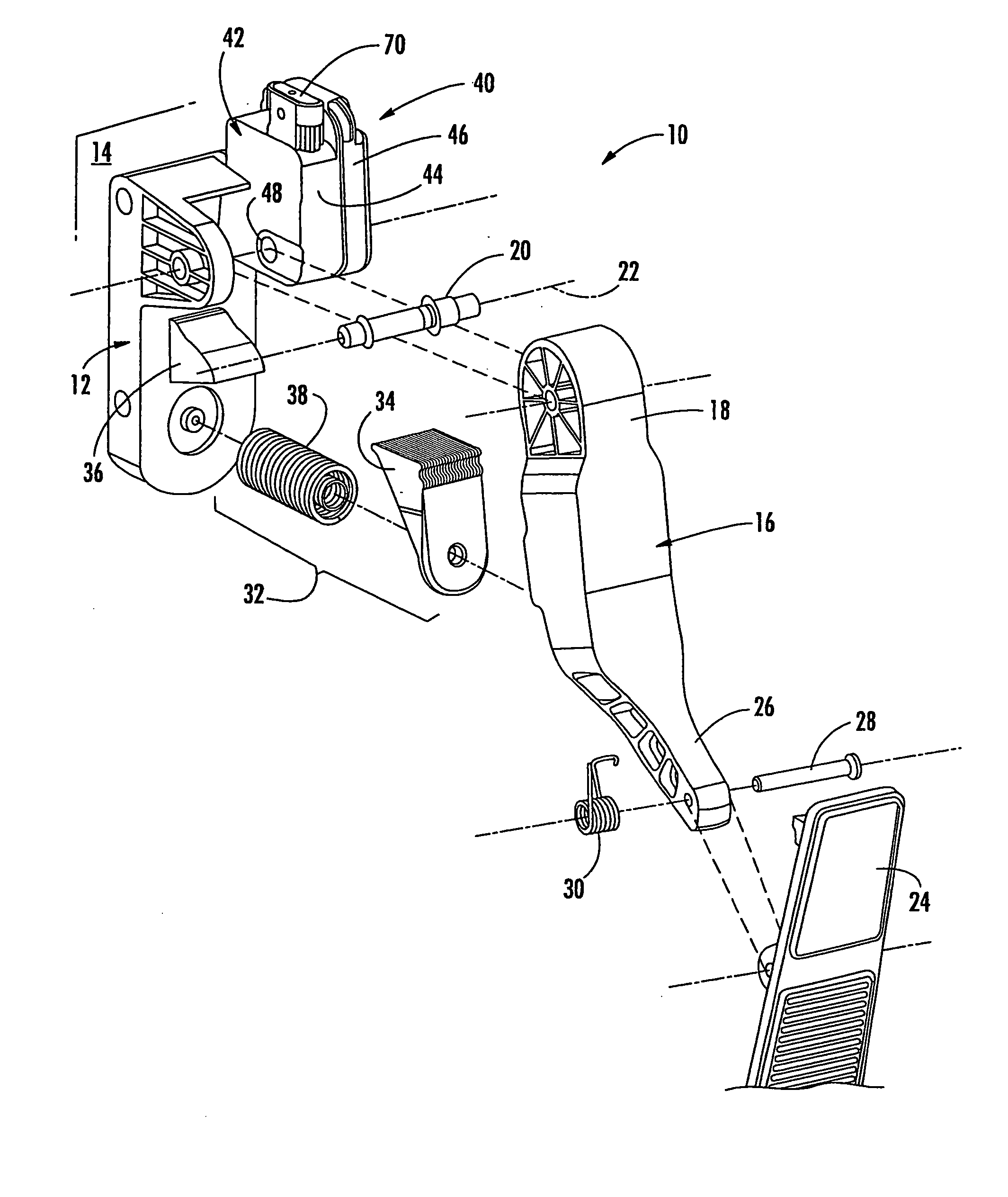
[0023] With reference initially to FIG. 1, one embodiment of the present invention is herein described for an electronic throttle control pedal assembly 10 comprising a mounting bracket 12 for mounting the pedal assembly to a vehicle wall 14, by way of example. A pedal beam 16 is rotatably attached to the mounting bracket 12 at a proximal end 18 using a shaft 20 which rotates about its longitudinal axis 22 in response to a rotation of the pedal beam abou...


PUM

PropertyMeasurementUnit
lengthaaaaaaaaaa
physical movementaaaaaaaaaa
electrical voltageaaaaaaaaaa

Abstract

A position sensor for an electronic control pedal is carried by the pedal mounting bracket and includes a linear potentiometer having a slider operable along a substrate in only a linear direction for providing an output voltage representative of slider displacement. A drive arm is connected to the pedal shaft for rotation during pedal movement. A coupler connected to the slider is slidable within a slot in the drive arm for providing the linear displacement through a rotational movement of the shaft. The drive arm has an inner arm in a telescoping connection with an outer arm for setting the drive arm at a desired length after potentiometer calibration. The longitudinal axis of the slot is at an non-zero angle to the longitudinal axis of the drive arm for desensitizing the sensor calibration and adjustment process.

Description

CROSS-REFERENCE TO RELATED APPLICATIONS [0001] This application is a continuation of U.S. application Ser. No. 10 / 218,672, filed Aug. 14, 2002 which itself is a divisional of U.S. application Ser. No. 09 / 698,581, filed Oct. 27, 2000 and issuing as U.S. Pat. No. 6,460,429 for “Electronic Control Pedal and Position Sensing Device and Assembly Method,” which claims the benefit of U.S. Provisional Application No. 60 / 162,609 filed Oct. 29, 1999 all commonly owned, disclosures of which are hereby incorporated by reference.FIELD OF THE INVENTION [0002] The present invention relates to electronic throttle control devices and in particular to an electronic sensor for indicating pedal position to an electronic throttle controller. BACKGROUND OF THE INVENTION [0003] Electronic controls and computers are well known in the art of automotive manufacturing. It is not unusual for a late model automobile to have a computer for monitoring and controlling many of its operating systems. Typically an in...

Claims


Application Information

Patent Timeline
Patent Type & Authority Applications(United States)
IPC IPC(8): B60K26/02F02D11/10B60K26/04G05G1/30G05G1/38G05G1/46
CPCB60K26/021Y10T29/49002F02D2011/102F02D2200/602G05G1/30G05G1/38G05G1/46Y10T29/49007Y10T74/20528Y10T29/49004Y10T74/2054Y10T74/20534Y10T74/20888Y10T29/49824Y10T29/49169F02D11/106G01D2205/22
Inventor STAKER, WILLIAM C.
Owner STAKER WILLIAM C
Why Eureka
Try Eureka