
Crystallizer molten steel level correction method

A calibration method and crystallizer technology, which is applied to liquid level indicators, instruments, machines/engines, etc., can solve the problems that the installation positions cannot be guaranteed to be completely consistent, and can not be guaranteed, so as to improve detection accuracy, improve accuracy, reduce The effect of small correction errors

Inactive Publication Date: 2021-01-01
ZHANGJIAGANG HONGCHANG STEEL PLATE CO LTD +1
View PDF6 Cites 0 Cited by
  • Summary
  • Abstract
  • Description
  • Claims
  • Application Information

AI Technical Summary

Problems solved by technology

Although the detection device has been improved to increase the detection sensitivity, when it is applied to a multi-strand continuous casting machine, it cannot guarantee that the installation position of the detection device on each stream is exactly the same, so it cannot be guaranteed that when the liquid level detection heights of the control streams are consistent, each The actual liquid level of the flow is also consistent

Method used


Image

  • Crystallizer molten steel level correction method
  • Crystallizer molten steel level correction method
  • Crystallizer molten steel level correction method

Examples


Embodiment 1

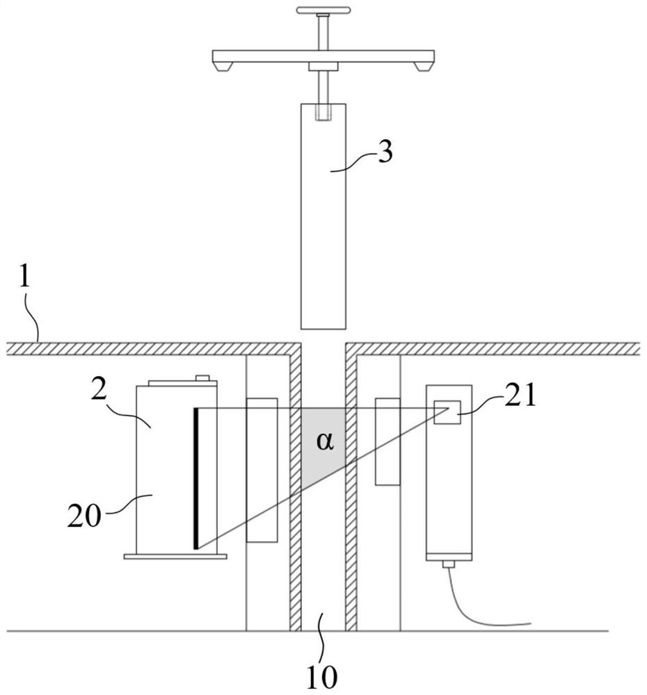
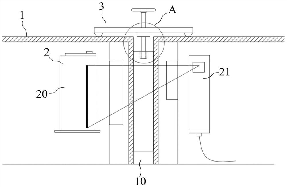
[0057] The mold steel liquid level correction method of the present embodiment adopts following correction device, and this device comprises:

[0058] Crystallizer 1, which is provided with crystallizer copper tube 10;

[0059] A liquid level detector 2, which includes a radiation source 20 arranged on one side of the mold copper tube 10 and a receiver 21 arranged on the other side of the mold copper tube 10;

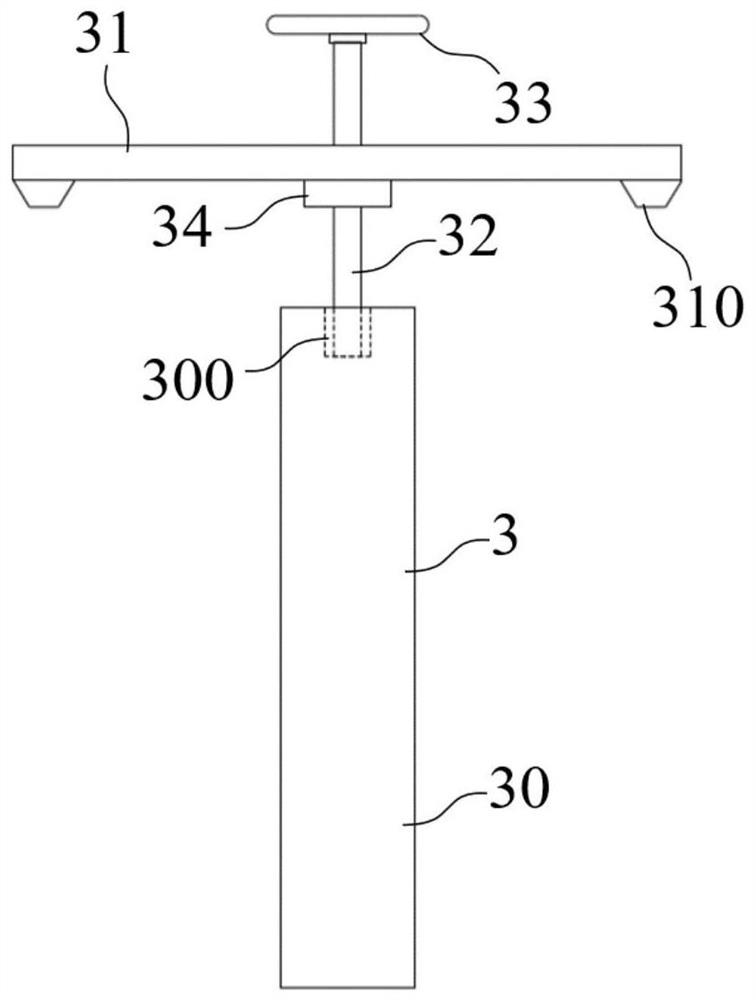
[0060] Also includes a correction device 3, which includes:

[0061] Billet mold 30, which is placed in the crystallizer copper tube 10;

[0062] Support frame 31, which is placed directly above the crystallizer copper tube 10;

[0063] Screw mandrel 32, which runs through support frame 31 and is threadedly connected with support frame 31, and one end of screw mandrel 32 is rotationally connected with billet mold 30 top;

[0064] The handwheel 33 is fixedly connected with the other end of the screw mandrel 32 .

[0065] In this embodiment, the structure of the corre...

Embodiment 2

[0069] This embodiment is further improved on the basis of Embodiment 1. The correction device 3 also includes a support frame slider 34, which is fixedly connected to the bottom of the support frame 31, and the screw rod 32 runs through the support frame slider 34 and slides with the support frame. Block 34 threaded connection.

[0070] Such as figure 2 Shown, by arranging support frame slide block 34, increase the screw connection length between screw mandrel 32 and support frame 31 and support frame slide block 34, because billet mold 30 weight is bigger, set up support frame slide block 34, evenly share the support frame The downward load borne by the threads of 31 reduces the resistance when the screw mandrel 32 rotates, facilitates the adjustment of the height of the billet mold 30 by the rotation of the handwheel 33, and further facilitates the correction operation.

Embodiment 3

[0072] This embodiment is further improved on the basis of Embodiment 2. The support frame 31 further includes a buffer seat 310, which protrudes downwards and is formed on the bottom surface of the support frame 31. The buffer seat 310 is an elastic structure.

[0073] The steel billet mold 30 has a relatively high mass. When the support frame 31 is placed, the buffer seat 310 composed of an elastic structure can effectively buffer and prevent the deformation of the support frame 31 under impact force from affecting the accuracy of subsequent calibration operations.

[0074] Further, the buffer seat 310 can be an elastic structure with a buffer function such as a spring.


PUM


Abstract

The invention discloses a crystallizer molten steel level correction method, and belongs to the technical field of continuous casting. The crystallizer molten steel level correction method comprises the following steps: 1, molten steel simulation: placing a steel billet die made of a steel billet in a crystallizer copper pipe, and enabling the upper surface of the steel billet die to be positionedin an effective monitoring area of a liquid level detector; 2, starting detection: starting the liquid level detector, detecting the position height of the upper surface of the steel billet die and displaying a detection result on intelligent terminal equipment; 3, marking a reference surface: marking the displayed position of the upper surface of the steel billet die as the reference surface through the intelligent terminal equipment; and 4, multi-flow correction: repeating the steps 1 to 3 for a crystallizer of each flow, and obtaining a corresponding reference surface for each flow. The correction method is simple in step and easy to operate, the steel billet die with the stable shape and structure is adopted for simulating molten steel for detection, the reference surface of each flowliquid level detector is conveniently and effectively corrected, then the accuracy of molten steel level control of each flow is ensured, and the product quality of a continuous casting system is improved.

Description

technical field [0001] The invention belongs to the technical field of continuous casting, and more specifically relates to a method for correcting the molten steel level of a crystallizer. Background technique [0002] In metallurgical continuous casting, mold liquid level control is one of the important factors to ensure the quality of continuous casting, especially for multi-strand continuous casting machines, in order to ensure product quality, it is necessary to unify the liquid level of each stream of molten steel in the copper tube The location is the same. [0003] The molten steel level in the mold is usually detected by radioactive sources and receivers. For multi-strand continuous casting systems, radioactive sources or receivers need to be replaced when they are damaged, and they also need to be disassembled during overhaul. When installing , it is impossible to ensure that the position of the radioactive source or receiver of each stream is installed consistent...

Claims


Application Information

Patent Timeline
Patent Type & Authority Applications(China)
IPC IPC(8): B22D11/18B22D2/00G01F23/288
CPCB22D2/00B22D11/18G01F23/288
Inventor 盛伟
Owner ZHANGJIAGANG HONGCHANG STEEL PLATE CO LTD
Learn More