Landscape edging, and methods

a technology of landscape edging and concrete, applied in the field of concrete edging blocks, can solve the problems of difficult to straighten plastic, uneven edging, and inability to fix materials in straight lines or measured curves, and achieve the effects of easy initial installation, labor-intensive process, and easy later modification

Inactive Publication Date: 2005-02-17
HECTOR TILE
View PDF26 Cites 22 Cited by
  • Summary
  • Abstract
  • Description
  • Claims
  • Application Information

AI Technical Summary

Benefits of technology

[0014] A second object of the landscape edging blocks is to provide a landscape edging that is easy to initially install and easy to later modify, if desired. The edging of the present invention is an improvement over concrete landscape edging that is poured or cast in place with a machine, which is a labor intensive process. Individual blocks of edging allow for modifications in alignment and positioning of the edging, as compared to poured edging.
[0015] Another object is to provide an edging that is economical compared to the cast or poured in place edging.
[0016] Yet another object is to provide a landscape edging that is durable and attractive. The edging of the present invention is able to withstand lawn mowing equipment, which often damages flexible plastic edging. Additionally, the edging of the present invention is not damaged or displaced by soil movement due to frost heave. Cast in place concrete edging can often crack due to frost heave.
[0017] A further object is to provide an edging that facilitates landscape maintenance. The edging of the present invention preferably includes a mowing feature that allows the mower deck of a lawn mower to ride over the edging and thus eliminate the need for trimming.

Problems solved by technology

First, these edgings do not have a natural, orderly appearance that is aesthetically pleasing in a landscaping application, having instead a man-made appearance.
Also, these materials are not easily fixed in straight lines or measured curves due to their flexible nature.
Many times, the plastic is difficult to straighten after having been packaged coiled or wound.
Further, materials are readily susceptible to damage during lawn mowing, digging, and other activities where sharp objects may contact the material, especially the plastic material.
Additionally, such edgings are susceptible to heaving from frost action in climates where the ground freezes.
However, the edging system disclosed in U.S. Pat. No. 4,976,063 still has some drawbacks, for example, the system does not allow for measured curves or allow for adjustments in the alignment between individual components.
Natural stone has long been used for this application, however natural stone typically has irregular shapes and requires labor-intensive fitting of the natural stones along the border or edging, or costly cutting of the pieces to fit.
The irregularity also makes natural stone difficult to accommodate lawn mowing.
Rectangular blocks do not lend themselves to the construction of curvilinear edgings, which are found in most landscaping applications, because they must be cut to avoid gaps that may allow penetration of grass roots or other vegetation and to provide an orderly appearance.
The disadvantages of this method are the expense and effort involved.
Such edgings may also require the placement of expansion material filled joints, and are susceptible to cracking.
In addition, such edgings are not readily removed in the event a change in the contour of the lawn or garden border is desired.
Finally, such edgings do not provide a desirable natural appearance.
Such curbing suffers from many of the limitations discussed above regarding edging, e.g., lack of curvilinear construction without time-consuming and costly on-site cutting, and susceptibility to heaving from freeze / thaw cycles.
For similar reasons, pavers and their edge restraints are also difficult to fix in straight measured curves, and are susceptible to heave from freeze / thaw cycles.

Method used


Image

  • Landscape edging, and methods
  • Landscape edging, and methods
  • Landscape edging, and methods

Examples


Embodiment Construction

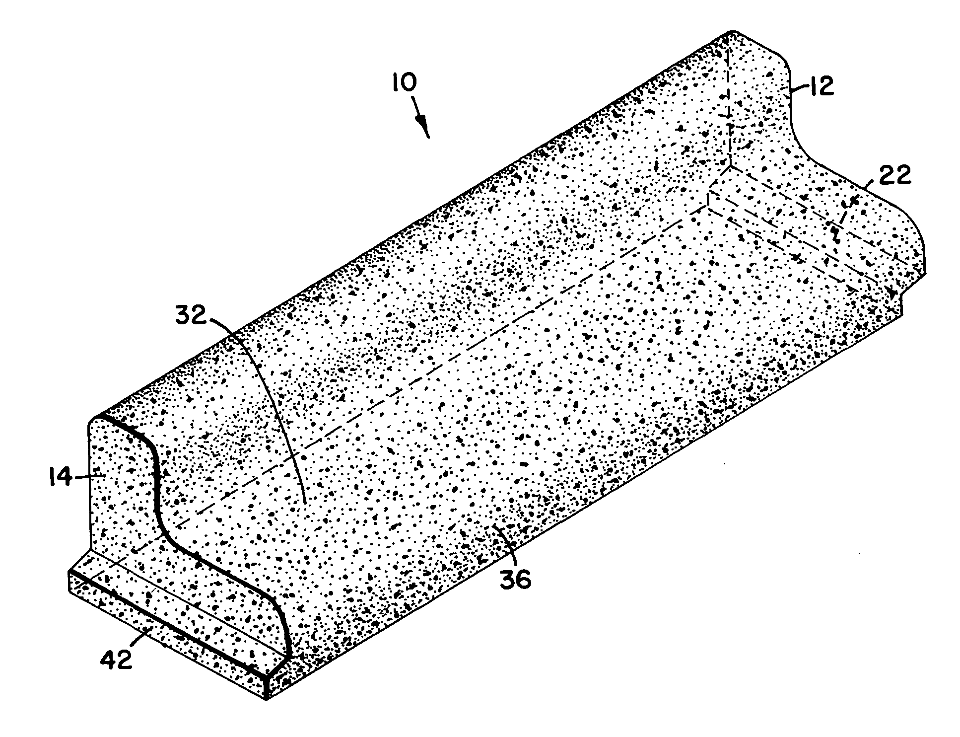
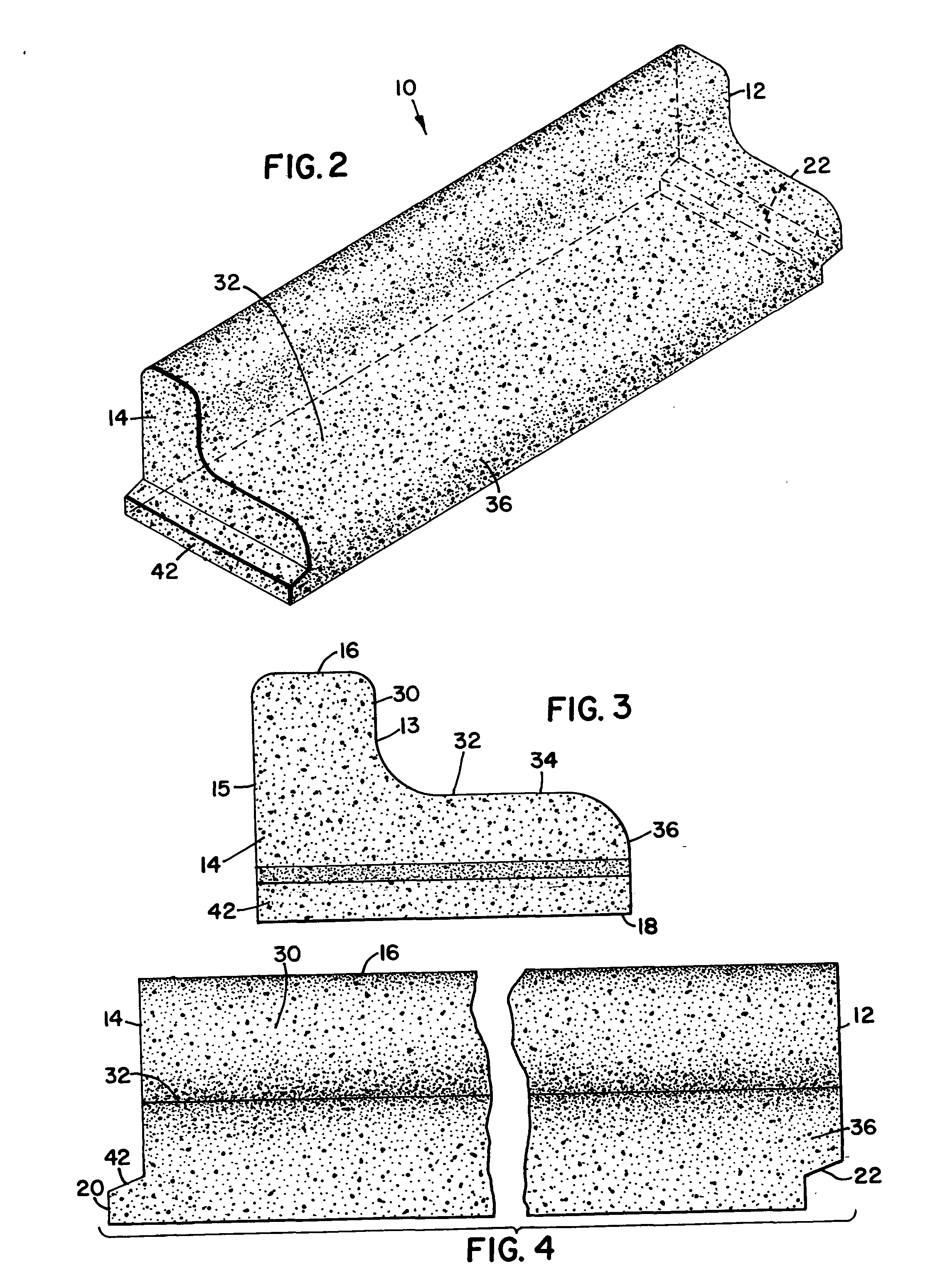
[0041] Referring to the figures there is generally illustrated therein a preferred embodiment of a landscape edging that incorporates the principles of this invention. While the preferred embodiment of the invention will be described in association with its applicability to landscape edging, it will be understood that the broad principles of the invention are not limited to such products or to the specifics of the preferred embodiment machine disclosed. The described edging represents one clear example incorporating the principles of the claimed invention, but the invention is not intended to be construed in a limiting manner as a result of the preferred embodiment disclosure.

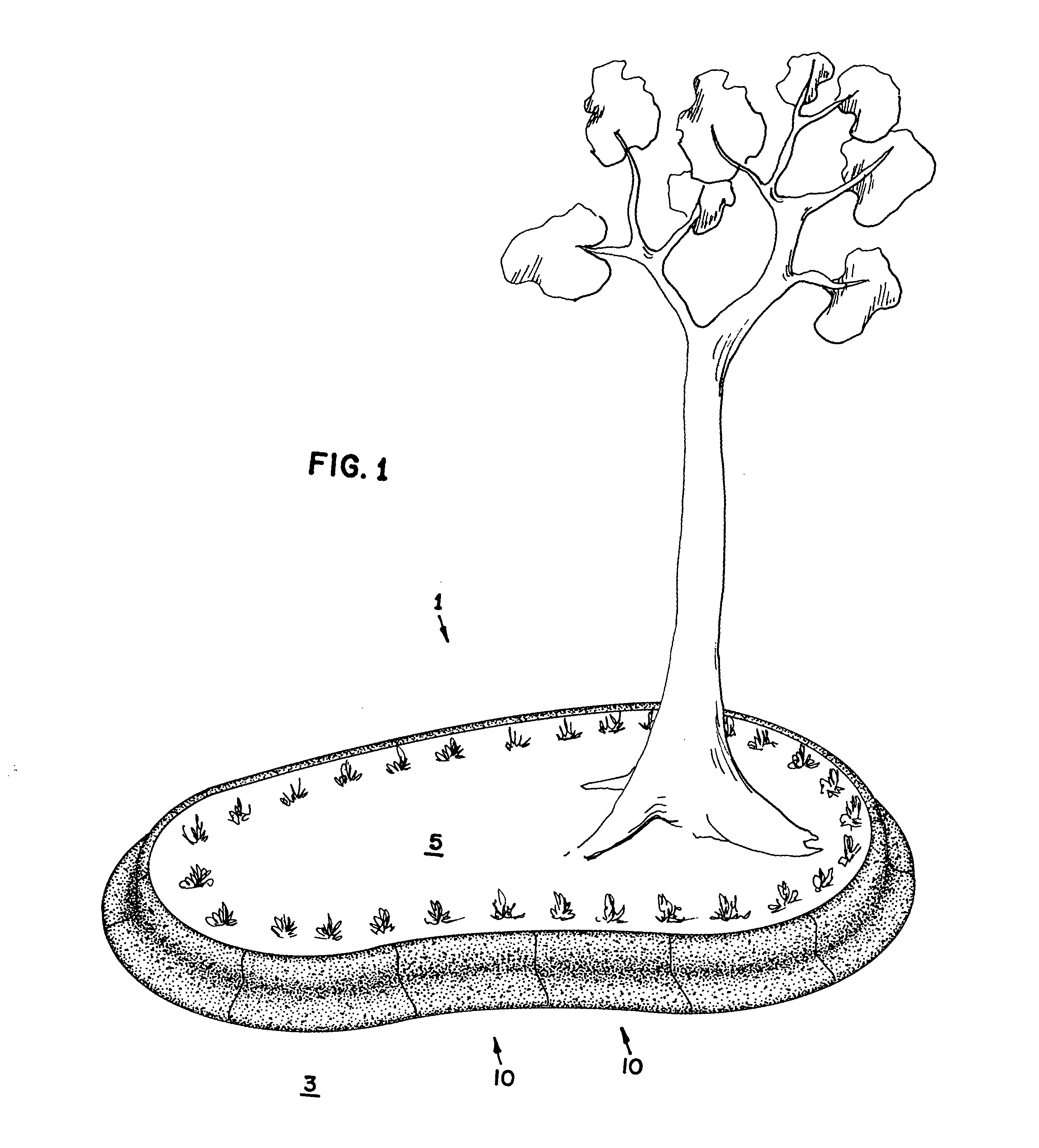
[0042] In FIG. 1 there is illustrated a typical application for landscape edging according to the present invention. Continuous edging 1, made of multiple edging blocks, such as edging block 10 according to the present invention, is installed to provide a separation or break between two areas 3, 5, one of the ...


PUM


Abstract

The disclosure is directed to landscape edging, such as blocks. Multiple blocks can be assembled to form a border around flower beds, trees, and other landscaping. A first end of the edging block includes a groove or mortise engageable with a second end of a second edging block having a tongue or tenon. The overlapping system inhibits growth of grass or other vegetation between two adjoining blocks. The edging includes a lip on at least one side that may function as a mowing strip or ledge. The block may be straight or curved, thus allowing multiple blocks to be assembled to form various configurations.

Description

FIELD OF THE INVENTION [0001] The invention relates to concrete edging blocks for use in landscaping and other applications. A first end of the edging block includes a first portion of an engagement system engageable with a second end of a second edging block having a second portion of the engagement system. The edging block includes a lip on at least one side that may function as a mowing strip. BACKGROUND OF THE INVENTION [0002] Numerous methods and materials exist for the construction of borders or edging for landscaping or site improvement work. Such borders or edges serve several functions. First, they are decorative, and provide an orderly transition from a garden area to a lawn, or from a lawn to a sidewalk, etc. Second, they serve to separate different areas with different forms of vegetation or other landscaping elements, thereby reducing maintenance requirements such as removing weeds, or trimming back vegetation that would otherwise spread. Third, they can ease the proces...

Claims


Application Information

Patent Timeline
Patent Type & Authority Applications(United States)
IPC IPC(8): A01G9/28
CPCA01G1/08A01G9/28
Inventor ANDERSON, MARK CARLTONANDERSON, DWIGHT DAVIDANDERSON, PAUL NEWTON
Owner HECTOR TILE
Why Eureka
Try Eureka