One-way clutch device and method for maufacturing the same

Inactive Publication Date: 2005-02-17
NSK WARNER
View PDF10 Cites 39 Cited by
  • Summary
  • Abstract
  • Description
  • Claims
  • Application Information

AI Technical Summary

Benefits of technology

[0010] The present invention has been contrived taking the situation described above into consideration, and an object of the invention is to provide a one-way clutch device with the intention of improving the strength of the coupling columns, preventing a fall out of

Problems solved by technology

However, when this clutch device is used in a starter apparatus for an automatic two-wheeled vehicle in which the maximum number of rotation of the internal combustion engine is comparatively high which is, e.g., 15,000 rpm or around, such a problem as described below may be brought about.
Moreover, since the centrifugal force acting on the spring becomes larger in the same manner, the spring may come off the cage so that its function of urging th

Method used


Image

  • One-way clutch device and method for maufacturing the same
  • One-way clutch device and method for maufacturing the same
  • One-way clutch device and method for maufacturing the same

Examples


first embodiment

[0053] (First Embodiment)

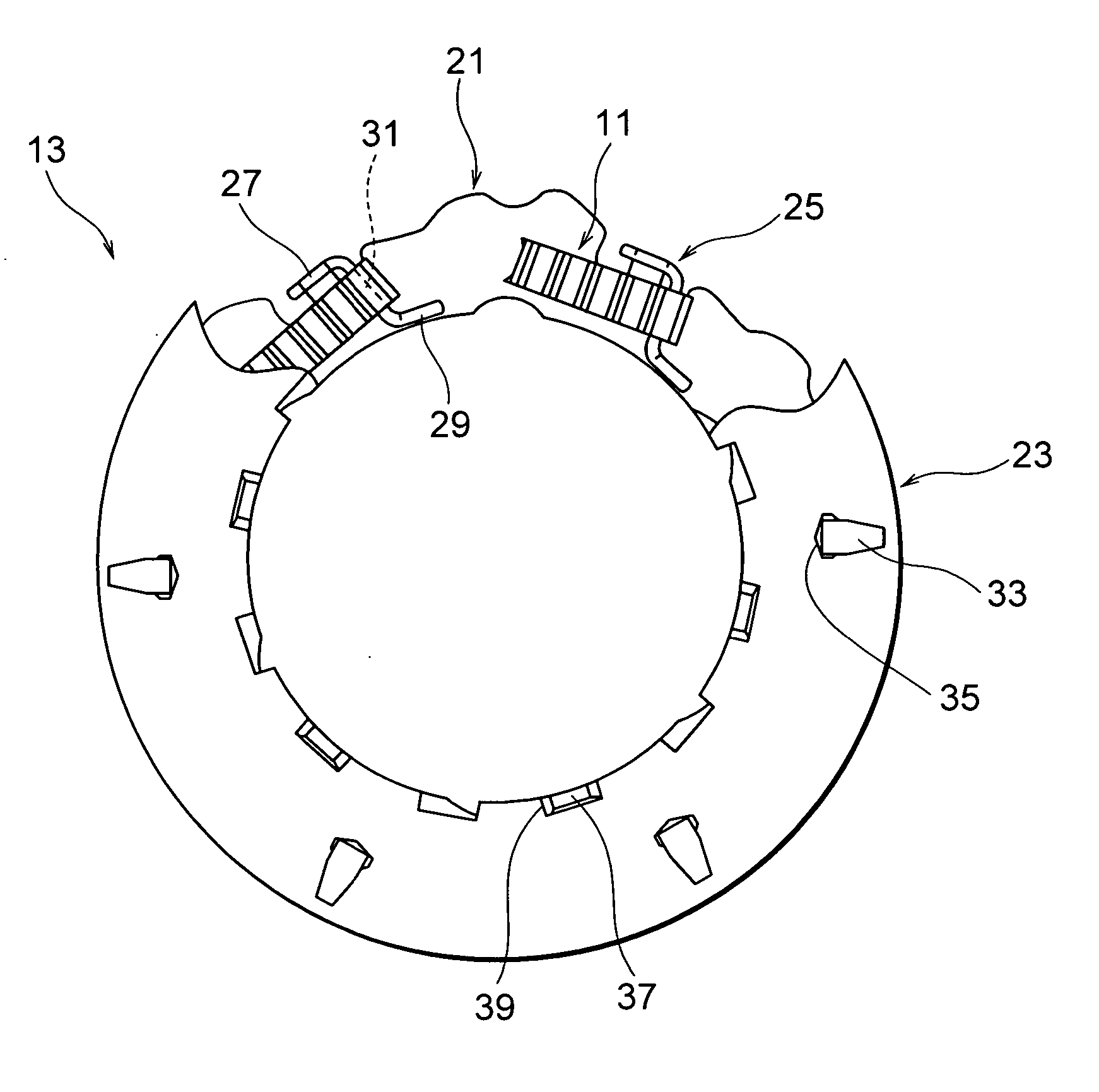
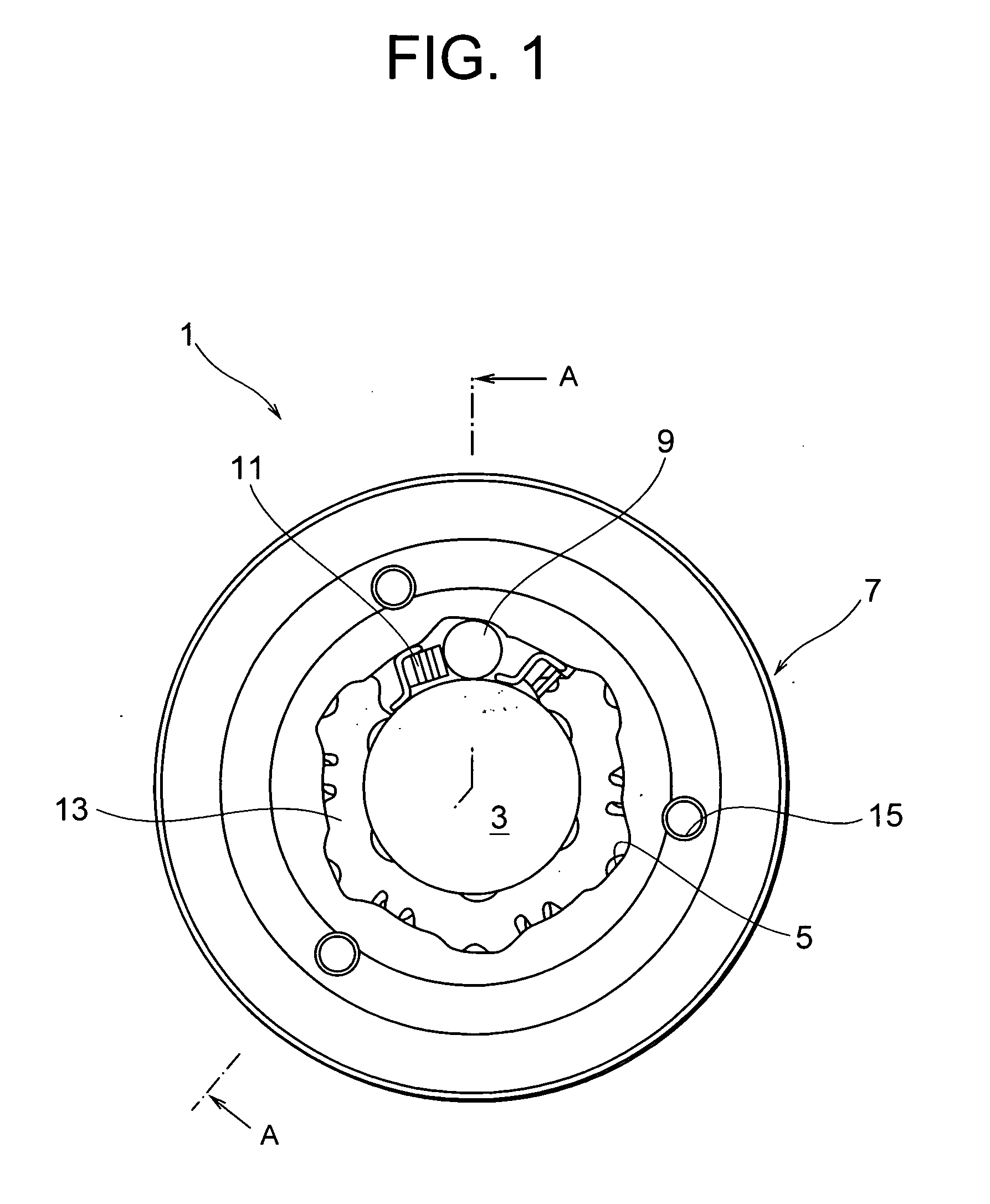
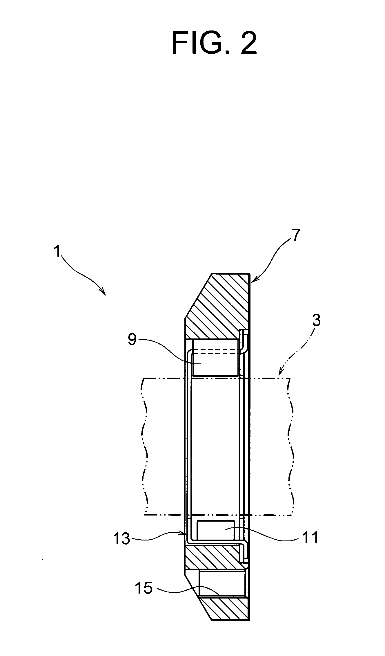
[0054]FIG. 1 is a front view for showing a first embodiment of a one-way clutch device according to the present invention, and FIG. 2 is a cross-sectional view taken along line A-A in FIG. 1. Also, FIG. 3 is a front view of a cage, and FIG. 4 is an enlarged view of an essential portion of the cage.

[0055] As shown in FIG. 1 and FIG. 2, the one-way clutch device 1 of the present invention is comprised of an inner race member (inner race element) 3, an outer race member (outer race element) 7 which is disposed coaxially with and relatively rotatable with respect to the inner race member 3 and is provided with a plurality of cam surfaces 5 (six in the present embodiment) formed on the inner periphery thereof, a plurality of torque transmission rollers 9 (six in the present embodiment) which are interposed between the inner race member 3 and the outer race member 7, accordion springs 11 for urging respectively the torque transmission rollers 9 in the direction o...

second embodiment

[0067] (Second Embodiment)

[0068]FIG. 12 is a front view of a one-way clutch device according to a second embodiment of the present invention, FIG. 13 is a cross-sectional view taken along line B-B in FIG. 12, and FIG. 14 is a partially exploded front view of the cage shown in FIG. 12. FIG. 15 is an enlarged view for showing an essential portion of the cage shown in FIG. 12.

[0069]FIG. 16 is a developed view of the cage on the first flange side. FIG. 17 is a front view of the cage on the second flange side. FIG. 18 is a plan view of an urging spring which is an accordion spring.

[0070]FIG. 19 is an enlarged cross-sectional view of the portion C in FIG. 13. FIG. 20 is an enlarged view for showing a detention piece and a detention portion of a recess, seen from the inner diameter side outwardly in the radial direction. FIG. 21 is an enlarged view for showing the detention piece and the detention portion of the recess, seen from the front.

[0071] The second embodiment is obtained by imp...


PUM

PropertyMeasurementUnit
Circumferenceaaaaaaaaaa
Torqueaaaaaaaaaa

Abstract

A one-way clutch device comprises a plurality of torque transmission members interposed between an inner race element and an outer race element for performing torque transmission therebetween only during one-way relative rotation. A cage has a pair of flanges for holding the torque transmission members therebetween and a plurality of coupling columns for coupling the paired flanges together. The coupling columns of the cage are fixed to fixing portions provided on an inner peripheral side and an outer peripheral side of the flanges.

Description

[0001] This application claims the benefit of Japanese Patent applications No. 2003-039933 and No. 2003-173720 which are hereby incorporated by reference. BACKGROUND OF THE INVENTION [0002] 1. Field of the Invention [0003] The present invention relates to a one-way clutch device which is assembled in a starter apparatus, or the like, for an automatic two-wheeled vehicle, and a method for manufacturing the same. [0004] 2. Related Background Art [0005] A starter apparatus for an automobile is additionally provided with a one-way clutch device for performing torque transmission from an electric motor side to an internal combustion engine side only, in order to prevent overrun of the electric motor after the internal combustion engine is started. As a one-way clutch device of this type, one type is dominantly used in which clutch elements such as torque transmission rollers, cam surfaces and a spring is interposed between an inner race element and an outer race element, and these clutch...

Claims


Application Information

Patent Timeline
IPC IPC(8): B21D39/02F16D41/06F16D41/066
CPCF16D2250/00F16D41/064F16D2041/0605
Inventor TAKASU, YASUHIDE
Owner NSK WARNER
Why Eureka
Try Eureka